Measurement Computing DBK Part 2 User Manual
Page 180
pg. 6, DBK90
907492
DBK Option Cards and Modules
Mounting one or two DBK90 Modules to a Primary Data Acquisition Device –
Using Kit # 1109-0802
Note: Kit 1109-0802 is for use with a primary data acquisition device that has
no molded protective ears. The ears would interfere with the kit’s splice plates.
Mounting kit p/n 1109-0802 includes two splice plates and the associated screws for securing the plates to
the main data acquisition device, and then securing up to two DBK90 modules to the plates. An optional
handle can be added, as discussed in step 1.
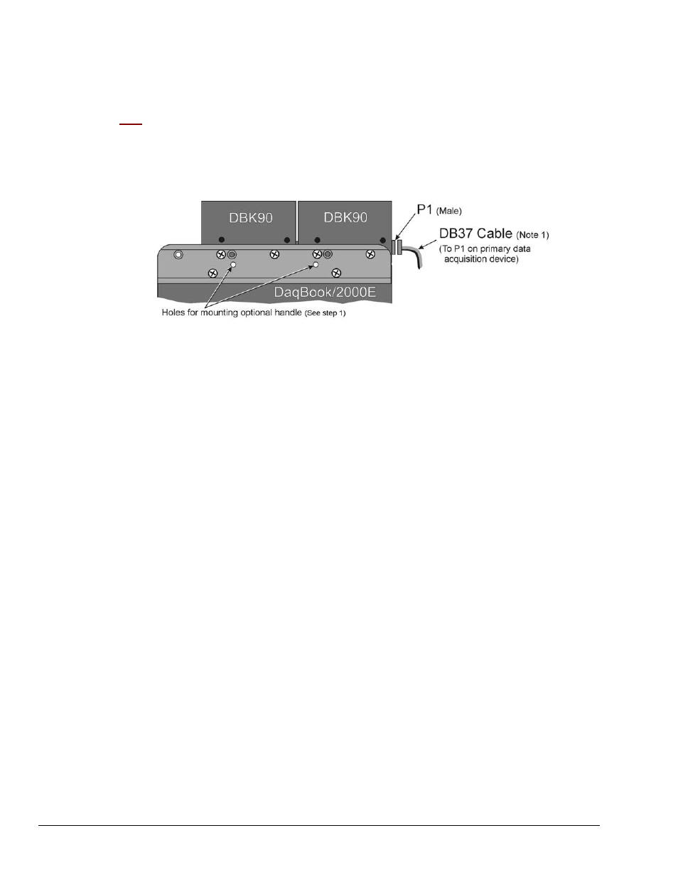
Two DBK90 Modules mounted to a DaqBook/2000E, via Kit # 1109-0802
Note that the DaqBook/2000 Series devices and the kit’s splice-plates each have a length of 8.5 inches.
1. If you are attaching an optional handle:
(a) Position the handle’s mounting holes over the indicated holes in one splice plate.
(b) Secure the handle by threading screws through the counter-sunk holes on the opposite
side of the splice plate.
2. Align the lower two screw-holes of one splice-plate with the mating holes on the primary
acquisition device.
3. Secure the splice-plate using two of the provided screws. The screws are 8-32 x 1/4 Phillips
Pan Head Screws.
4. Mount the second splice-plate to the other side of the acquisition device.
5. Position a DBK90 module such that its male P1 connector is located on the same plane as the
P1 connector on the primary device.
6. With the screw holes of the DBK90 aligned with those of a splice-plate (see figure), secure the
module to the plate. Repeat this step for the other side of the module.
7. If you are connecting a second DBK90 module:
(a) Mate the male P1 connector of the second DBK90 module with the female P1
connector of the first DBK90 module.
(b) Secure the second DBK90 module to the two splice plates using two screws per side
(see figure).
8. Connect one end of a DB37 cable to the first DBK90’s P1 male connector (see figure).
9. Connect the other end of the CA-37 cable to the male P1 connector of the data acquisition
device.
This completes the procedure.
Note 1: A female-to-female 37 pin connector can be used to connect a DBK90 to the host data
acquisition device. The use of a CA-143-x shielded cable is recommended for scenarios in
which signal noise is a problem. Page 14 of this section includes a list of cables compatible
with DBK90 use.