Measurement Computing DBK Part 2 User Manual
Page 154
Using the Connection POD, DBK83 Only
Unlike other DBK units, the input connections for the DBK83 do not exist on the card itself. Instead, they
exist in an external connection pod, POD-1. POD-1 simply represents a physical relocation of the input
screw terminals and cold junction sensors that reside on the card in the case of the DBK81 and DBK82.
POD-1 connects to the DBK83 unit via the CA-239 cable. POD-1 dimensions are provided at the end of
this section.
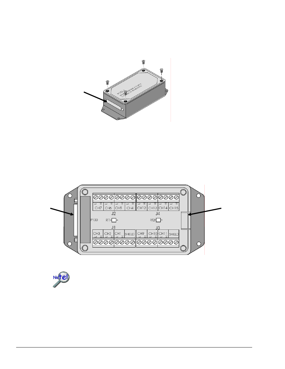
You must remove the four cover screws
and the cover plate to access the pod’s
terminal blocks. The terminal block
layout is provided in the following
figure.
The female-end of the CA-239
cable connects to POD-1’s
male 44-pin connector.
POD-1
To install thermocouple wires in POD-1:
1.
Remove the four screws of the POD-1 cover.
2.
Route the thermocouple wires through the input hole of the POD-1 and connect them to the
intended channels. Note the “H” and “L” polarity designations on the channels for proper
connection. (See the following figure).
3.
Replace the POD-1 cover and secure it with the four screws that were removed in step 1.
The CA-239
cable connects
here.
Thermocouple wires route
through this opening.
POD-1 Connection Terminals
For isothermal performance, an exposed, grounded copper plane surrounds the input
connectors. It is important that non-insulated input wires do not contact the grounded
plane
− since such contact can degrade measurement integrity.
pg. 4, DBK81, DBK82, & DBK83
989494
DBK Option Cards and Modules