Measurement Computing DBK Part 2 User Manual
Page 54
DBK43A & DBK43B, pg. 34
899892
DBK Option Cards and Modules
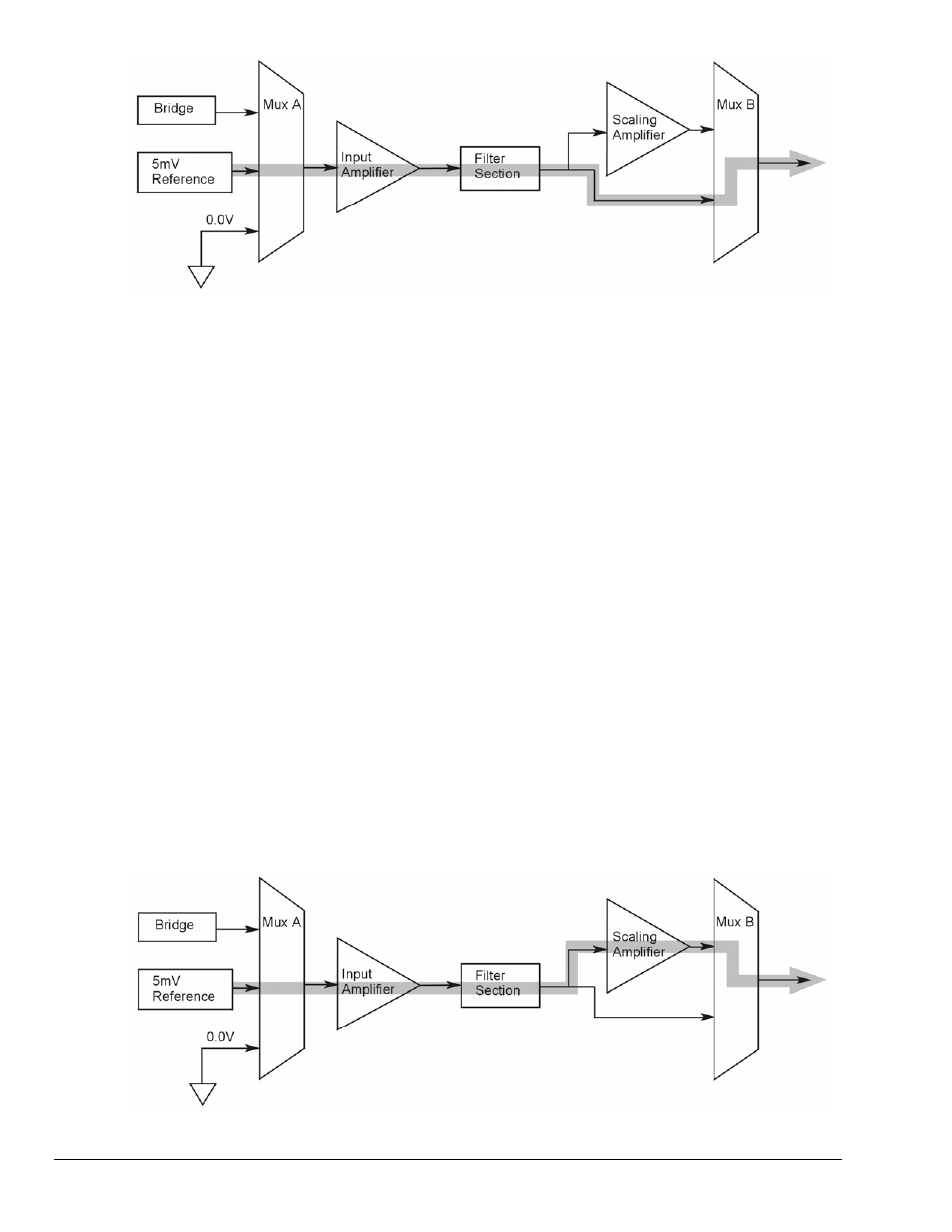
“Mode = SetInputGain,”
5 milli-Volt Reference Route
3. Turn off all the channels in the system except for those DBK43A channels that are to be
adjusted.
4. Click the Download button to send the current configuration to the LogBook.
5. Select Indicators \ Enable Input Reading Column from the menu bar to display the values for
each channel.
6. For the associated channel, set the voltage to [G
I
* G
F
* 0.005] for each transducer by
adjusting the trimpot labeled GAIN. Use the Input Amplifier Gain (G
I
) calculated earlier.
Note:
If the filter is enabled, the filter gain (G
F
) is 2; otherwise G
F
= 1.
Example 1:
If G
I
= 250 and the filter is disabled; the GAIN
trimpot would be adjusted to obtain 1.25V.
Example 2:
If G
I
= 250 and the filter is enable; the GAIN
trimpot would be adjusted to obtain 2.50V.
7. Select Indicators \ Disable Input Reading Column from the menu bar.
Adjust the Scaling Amplifier Gain
Adjust the Scaling Amplifier Gain as follows:
1. In the Param1 column (see page 27 for location), select all of the DBK43A channels that are
to be adjusted.
2. Select Mode = SetScalingGain from the drop down list above the grid. This selection
commands the calibration multiplexer to route a 5mV reference through all of the
amplification stages as shown below.
“Mode = ScalingGain
,” 5 milli-Volt Reference Route