Hardware connection, Power connection, Caution – Measurement Computing DBK Part 2 User Manual
Page 23: Signal connection
DBK Option Cards and Module
899892
DBK43A & DBK43B, pg. 3
Hardware Connection
Power Connection
The strain gage modules each require an input
voltage between +9 and +18 VDC. The DC
source should be filtered but not necessarily
regulated — a DBK30A Rechargeable
Battery/Excitation Module is recommended for
portable use. The DBK43A and DBK43B strain
gage modules have an isolated DC/DC converter-
based power supply which provides all excitation
voltages and biasing for the amplifier circuits.
For both modules, each of eight on-board
excitation regulators can be adjusted from 1.5 to
10.5 VDC. These outputs have remote sensing terminals and feature 50 mA current limiting to prevent
damage from short-circuit or overload. The regulators’ wide voltage range can accommodate any resistive
or semi-conductive gage type.
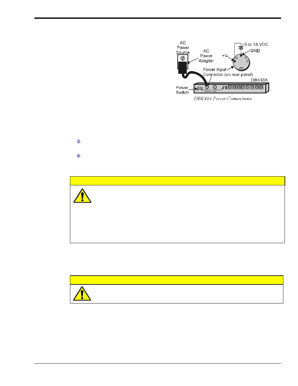
The DBK43A and DBK43B can be powered with an AC adapter or from any isolated 9-18 VDC source of
16 W (see figure). Before plugging unit in, make sure the power switch is in the “0” (OFF) position.
If using an AC power adapter, plug it into an AC outlet and attach the low voltage end to the jack
on the DBK43A or DBK43B, as applicable.
If using a different 9 VDC to 18 VDC source, make sure the leads are connected to the proper
DIN terminals. Power connections for DBK43A and DBK43B are the same.
CAUTION
POWER IN : The power connectors are rated at 5 amps maximum DC current. The
power supply provided with the module can power the unit but not any auxiliary
devices. If using the unit’s power supply, do not use the POWER OUT terminal.
If using another power supply to power auxiliary devices from the POWER OUT
terminal, make sure that power supply is current-rated for the units connected
(up to 5 amps DC).
POWER OUT : Maximum output current is 3 amps DC. Use a power supply capable of
supplying 5 amps DC at POWER IN.
Signal Connection
CAUTION
The maximum channel signal input from plus Voltage (+V) to minus Voltage (-V) is
50 mV. There is no common-mode isolation between inputs (common-mode voltage
between inputs must be 0 V).
The following two figures (next page) each represent one of the 6-pin signal connectors located on the
back of a DBK43A (left figure) and DBK43B (right figure). Both configurations are for a full-bridge with
remote sensing.