Connecting the dbk65 to signals, Primary data acquisition device, And to the – Measurement Computing DBK Part 2 User Manual
Page 137: Caution
Connecting the DBK65 to Signals
and to the
Primary Data Acquisition Device
You can connect the DBK65 module to your primary data acquisition device and to its signal inputs after
you have completed the following:
•
set the DBK65 module’s address
•
configured the DBK65 on a channel-by-channel basis for the application
•
configured the primary data acquisition device, if applicable
You can connect up to eight sensors to one DBK65. A CA-37-x, CA-131-x, or a CA-255-xT cable is used
to connect the module to a LogBook or Daq device via DB37 connectors (P1).
To connect a DBK65 to a WaveBook or ZonicBook, refer to the final portion of this section,
Connecting to
a BNC Connector
.
If your system needs to be CE Compliant, be sure to read the applicable Declarations of
Conformity prior to connecting the DBK65.
Connect the DBK65 module as follows.
1.
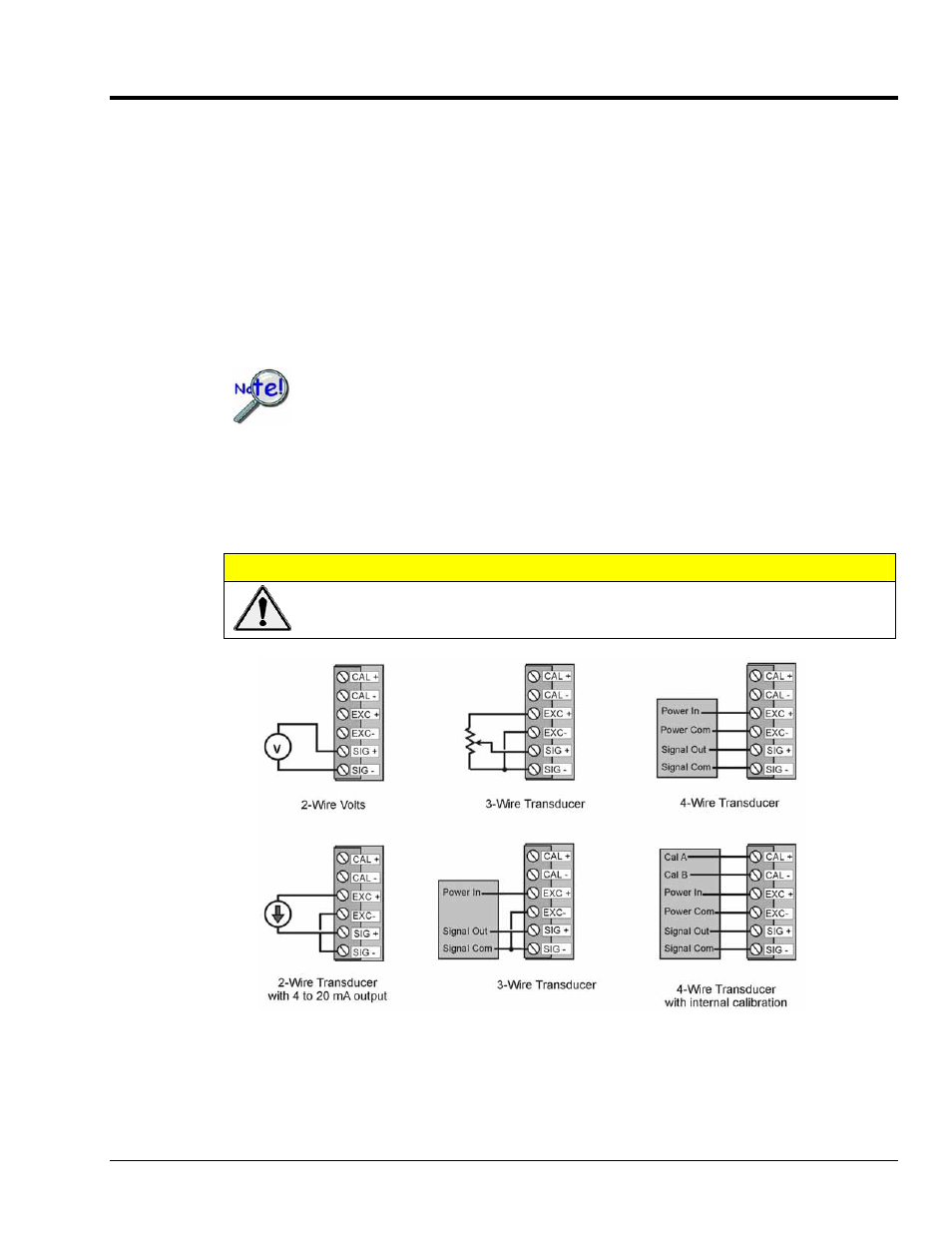
Connect each input to a screw terminal block on the DBK65. Example wiring diagrams are provided
below. Note that the screw-terminal blocks can be removed from the DBK65 to allow for easier
wiring.
CAUTION
Do not connect the excitation source to a non-isolated, powered transducer. Making
such a connection can cause damage to both the DBK65 and to the transducer.
Wiring Scenarios
A Note Regarding the Excitation Source
The excitation source is ground-referenced, not floating, i.e., the -Excitation (EXC -) terminal is connected
to the DBK65’s ground. The Excitation Source is designed to interface with transducers such that it is the
only power source, or its connection is electrically isolated from other power sources.
DBK Option Cards and Modules
988793
DBK65 pg. 9