Measurement Computing DBK Part 2 User Manual
Page 242
DBK208, pg. 6
987594
DBK Option Cards and Modules
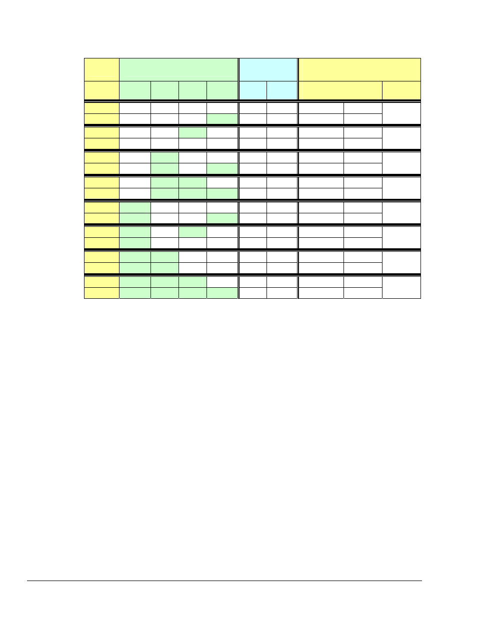
DBK208
Board #
Switch S1 Configurations
Address
Designation in
DaqView
(see notes 2 & 3)
16
8
4
2
Bank 0
Bank 1
Expanded Digital I/O in
Async Digital I/O window
Channel
0
OFF
OFF
OFF
OFF
0
1
P2 0-A
P2 0-B
1
OFF OFF OFF ON
2
3
P2 0-C
P2 0-D
0
2
OFF OFF ON
OFF
4
5
P2 1-A
P2 1-B
3
OFF OFF ON
ON
6
7
P2 1-C
P2 1-D
1
4
OFF
ON
OFF
OFF
8
9
P2 2-A
P2 2-B
5
OFF
ON
OFF
ON
10
11
P2 2-C
P2 2-D
2
6
OFF
ON
ON
OFF
12
13
P2 3-A
P2 3-B
7
OFF
ON
ON
ON
14
15
P2 3-C
P2 3-D
3
8
ON
OFF
OFF
OFF
16
17
P2 4-A
P2 4-B
9
ON
OFF OFF ON
18
19
P2 4-C
P2 4-D
4
10
ON
OFF
ON
OFF
20
21
P2 5-A
P2 5-B
11
ON
OFF
ON
ON
22
23
P2 5-C
P2 5-D
5
12
ON
ON
OFF
OFF
24
25
P2 6-A
P2 6-B
13
ON
ON
OFF
ON
26
27
P2 6-C
P2 6-D
6
14
ON
ON
ON
OFF
28
29
P2 7-A
P2 7-B
15
ON
ON
ON
ON
30
31
P2 7-C
P2 7-D
7
Notes:
(1) Switch S1 settings are made physically on the DBK208 boards and are checked in DaqView (see the
following screen capture). The software aspect is detailed on the following page.
(2)
The Digital Option Cards External Connection section of DaqView’s Configure System Hardware
window lists 8 channels (0 through 7) as shown in the following screen image.
(3)
Each of the 8 channels can represent 2 DBK208 boards. For example, as seen in the table, System Board
0 and System Board 1 would both show up in DaqView’s channel 0.
(4)
In the Async Digital I/O window, each active channel (representing 2 boards) has divisions of A, B, C,
and D. A represents Bank 0 of the first board. B represents Bank 1 of the first board.
C represents Bank 0 of the second board. D represents Bank 1 of the second board.
(5)
Banks are selected to be “Input” or “Output” via jumpers. Jumper JP0 applies to Bank 0, JP1 applies to
Bank 1.
Logic outputs provide signals for clocking data to registers for the Opto-22 SSR type modules. On-board
jumpers (JP0 and JP1) are used to set the banks for “input” or “output.” The banks can be set
independently, however, all modules within a bank will have the same setting. For example, JP0 could be
set to “Input,” configuring all 8 modules of Bank 0 to Input; and JP1 could be set to “Output,” configuring
all Bank 1 modules to “Output.”
Each Opto-22 module has a 2-connector terminal block for signal connections.