Hardware adjustment, Trimpots, Cal/norm, cal1/run, and cal2/run switches – Measurement Computing DBK Part 2 User Manual
Page 33
DBK Option Cards and Module
899892
DBK43A & DBK43B, pg. 13
2. For DaqBook/100, DaqBook/112 and DaqBook/120, place the JP4 jumper in single-ended mode
Note: To use a DBK43A [or DBK43B] with a Daq PC-Card, you must an appropriate power module must
be used.
DaqBook/2000 Series and DaqBoard/2000 Series Configuration
No Jumper configurations are required for these /2000 series devices.
Hardware Adjustment
Bridge circuit transducers are used for many different applications, and the DBK43A and DBK43B
modules are flexible enough to support most of them. Each channel circuit has an excitation regulator, a
high gain (100-1250) input amplifier with offset adjustment, a low-pass filter, a scaling (1-10) amplifier,
and a calibration multiplexer.
Trimpots
The front of the strain gage modules have a slot to allow access to 4 potentiometers to trim (adjust) the
accuracy for each channel circuit. The trimpots are labeled to represent the following adjustments:
EXC
for adjusting the excitation voltage to the transducer
GAIN
for setting the gain of the input amplifier
OFFSET for adjusting the circuit offset for quiescent loads or bridge imbalance
SCALE for setting the gain of the scaling amplifier
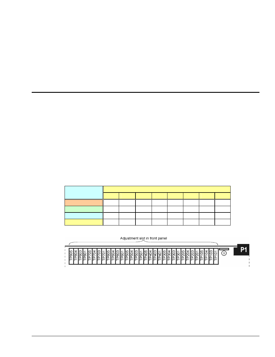
Channel Number
Trimpot
CH0
CH1
CH2
CH3
CH4
CH5
CH6
CH7
EXC
TP101 TP201 TP301 TP401 TP501 TP601 TP701 TP801
GAIN
TP104 TP204 TP304 TP404 TP504 TP604 TP704 TP804
OFFSET
TP103 TP203 TP303 TP403 TP503 TP603 TP703 TP803
SCALE
TP105 TP205 TP305 TP405 TP505 TP605 TP705 TP805
The following figure shows trimpot locations for both the DBK43A and DBK43B.
Trim Pot Locations
CAL/NORM, CAL1/RUN, and CAL2/RUN Switches
DBK43A has a single CAL/NORM switch. DBK43B has two switches, CAL1/RUN and CAL2/RUN.
The switches are easy to see on the rear panel of the associated DBK module.
• The NORM and RUN positions are for normal running operations, as indicated in the following
tables.
• In the CAL position, the shunt calibration offset and the excitation voltage can be read depending on
the software function control. This is discussed in the next section.