Measurement Computing DBK Part 2 User Manual
Page 285
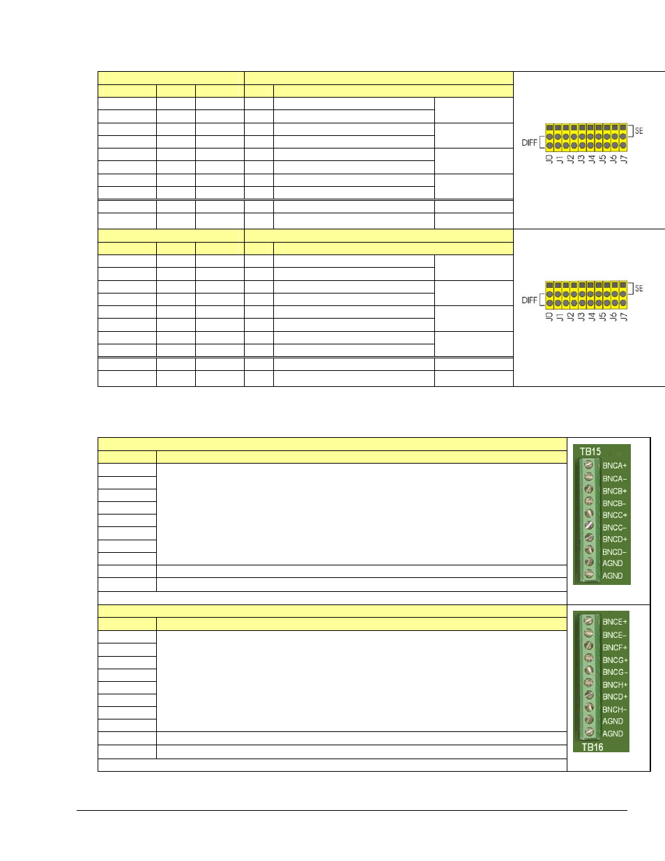
P1 Correlation to Analog Input BNC Terminations – BNC Ch 0 through BNC Ch 7
“Virtual” Terminal Blocks TB13 and TB14 for ANALOG INPUT connect to TB9 and TB10 through the printed circuit board.
TB13 (“Virtual” Terminal Block)
P1 Pin Number and Description
BNC CH
DIFF
SE
Pin SE = Single Ended ; DIFF = Differential Jumper Used
BNC0+
0H
0
37
CH 0 IN (SE) / CH 0 HI IN (DIFF)
BNC0-
0L
8
18
CH 8 IN (SE) / CH 0 LO IN (DIFF)
J0
BNC1+
1H
1
36
CH 1 IN (SE) / CH 1 HI IN (DIFF)
BNC1-
1L
9
17
CH 9 IN (SE) / CH 1 LO IN (DIFF)
J1
BNC2+
2H
2
35
CH 2 IN (SE) / CH 2 HI IN (DIFF)
BNC2-
2L
10
16
CH 10 IN (SE) / CH 2 LO IN (DIFF)
J2
BNC3+
3H
3
34
CH 3 IN (SE) / CH 3 HI IN (DIFF)
BNC0+
3L
11
15
CH 11 IN (SE) / CH 3 LO IN (D DIFF)
J3
AGND N/A N/A
* Analog
Ground
N/A
AGND N/A N/A
* Analog
Ground
N/A
TB13 does not physically exist on
DBK214. A silkscreen of TB13 is
present as a visual aid to signal
routing and configuration.
A header located beneath TB14 and
TB16 is used to set the BNC
channels to Single-Ended or to
Differential. Simply place channel’s
2-pin jumper in the appropriate
position (SE or DIFF).
TB14 (“Virtual” Terminal Block)
P1 Pin Number and Description
BNC CH
DIFF
SE
Pin SE = Single Ended ; DIFF = Differential Jumper Used
BNC4+
4H
4
33
CH 4 IN (SE) / CH 4 HI IN (DIFF)
BNC4-
4L
12
14
CH 12 IN (SE) / CH 4 LO IN (DIFF)
J4
BNC5+
5H
5
32
CH 5 IN (SE) / CH 5 HI IN (DIFF)
BNC5-
5L
13
13
CH 13 IN (SE) / CH 5 LO IN (DIFF)
J5
BNC6+
6H
6
31
CH 6 IN (SE) / CH 6 HI IN (DIFF)
BNC6-
6L
14
12
CH 14 IN (SE) / CH 6 LO IN (DIFF)
J6
BNC7+
7H
7
30
CH 7 IN (SE) / CH 7 HI IN (DIFF)
BNC7+
7L
15
11
CH 15 IN (SE) / CH 7 LO IN (DIFF)
J7
AGND N/A N/A
* Analog
Ground
N/A
AGND N/A N/A
* Analog
Ground
N/A
TB14 does not physically exist on
DBK214. A silkscreen of TB14 is
present as a visual aid to signal
routing and configuration.
A header located beneath TB14 and
TB16 is used to set the BNC
channels to Single-Ended or to
Differential. Simply place channel’s
2-pin jumper in the appropriate
position (SE or DIFF).
Correlation to Custom BNC Terminations – BNC Ch A through BNC Ch H
Pertains to Terminal Blocks TB15 and TB16 for Custom Configuration on a per-channel basis.
TB15 (“Routing” Terminal Block)
BNC CH
Description
BNCA+
BNCA-
BNCB+
BNCB-
BNCC+
BNCC-
BNCD+
BNCD+
BNC channels A through D are configured on a per-channel basis by the user. TB15 is a routing
terminal block used to connect BNCs (A thru D) to the desired signals, which are selected via a second
DBK214 terminal block. For example: a user could run a wire from BNCA+ to TB4 screw terminal
“TMR0” and BNCA- to TB4 DGND to create a BNC timer connection.
Accessory Wire Kit, p/n 1139-0800 includes jumper wires and a screwdriver.
AGND
Analog Ground *
AGND
Analog Ground *
TB15
TB16 (“Routing” Terminal Block)
BNC CH
Description
BNCA+
BNCA-
BNCB+
BNCB-
BNCC+
BNCC-
BNCD+
BNCD+
BNC channels E through H are configured on a per-channel basis by the user. TB16 is a routing
terminal block used to connect BNCs (E thru H) to the desired signals, which are selected via a second
DBK214 terminal block.
Customizing is as described for BNCA through BNCD above.
Accessory Wire Kit, p/n 1139-0800 includes jumper wires and a screwdriver.
AGND
Analog Ground *
AGND
Analog Ground *
TB16
DBK Option Cards and Modules
967894
DBK214, pg. 11