Overview – Measurement Computing DBK Part 2 User Manual
Page 208
pg. 2, DBK202, DBK203, and DBK204 Series
938994
DBK Option Cards and Modules
Overview
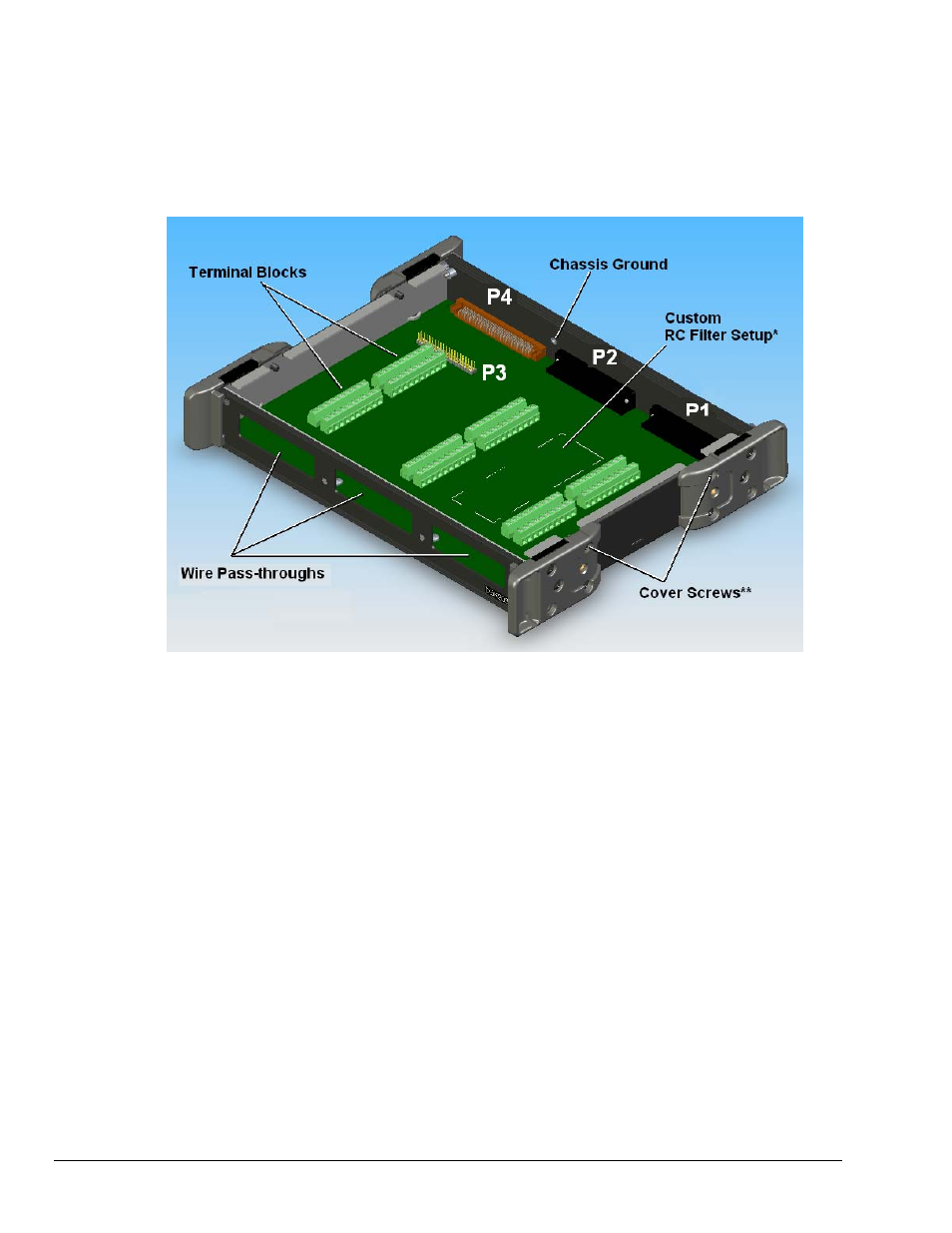
The various part numbers [DBK202, /203, /203A, /204, and /204c] of these closely related products are
described in the table on page 1. With exception of the DBK202 being a “board only,” the layout for each
is as indicated in the following figure.
DBK203A, Cover Plate Removed
* Custom RC Filter Setup is discussed in the section entitled, Adding Resistor/Capacitor Filter
Networks, page 12.
** To remove the cover plate, remove the upper inside screw from each of the corner mounting
brackets (often referred to as protective ears); then lift the plate from the unit.
The information included in this section, when combined with that found in related DBK card and DBK
module sub-sections should enable you to set up your desired configuration.
It is important to note that the DaqBoard/2000 Series boards communicate [external from the host PC]
through a 100-pin P4 connector. The P1, P2, and P3 connectors discussed in association with these boards
are subset connectors of the 100-pin P4 connector. Certain DaqBook/2000 Series devices have both a P4
connector and a set of P1, P2, and P3 connectors on the unit. The System Connections and Pinouts chapter
includes pinouts for both types of devices, i.e., boards and “books.”
Each of the adapters discussed in this section provide a DB37 P1 connector, DB37 P2 connector, and a
40-pin “on-board” P3 header.
o
P1 is used for Analog Input
o
P2 for Digital I/O
o
P3 for Pulse/Frequency (Digital and Counter/Timer) I/O
o
P4 includes all signals found in P1, P2, and P3
In addition to these four connectors, each device includes terminal blocks designated TB1 through TB12.
The screw terminal blocks tie-in to P1, P2, and P3 and provide for easy signal connection.