Measurement Computing DBK Part 2 User Manual
Page 117
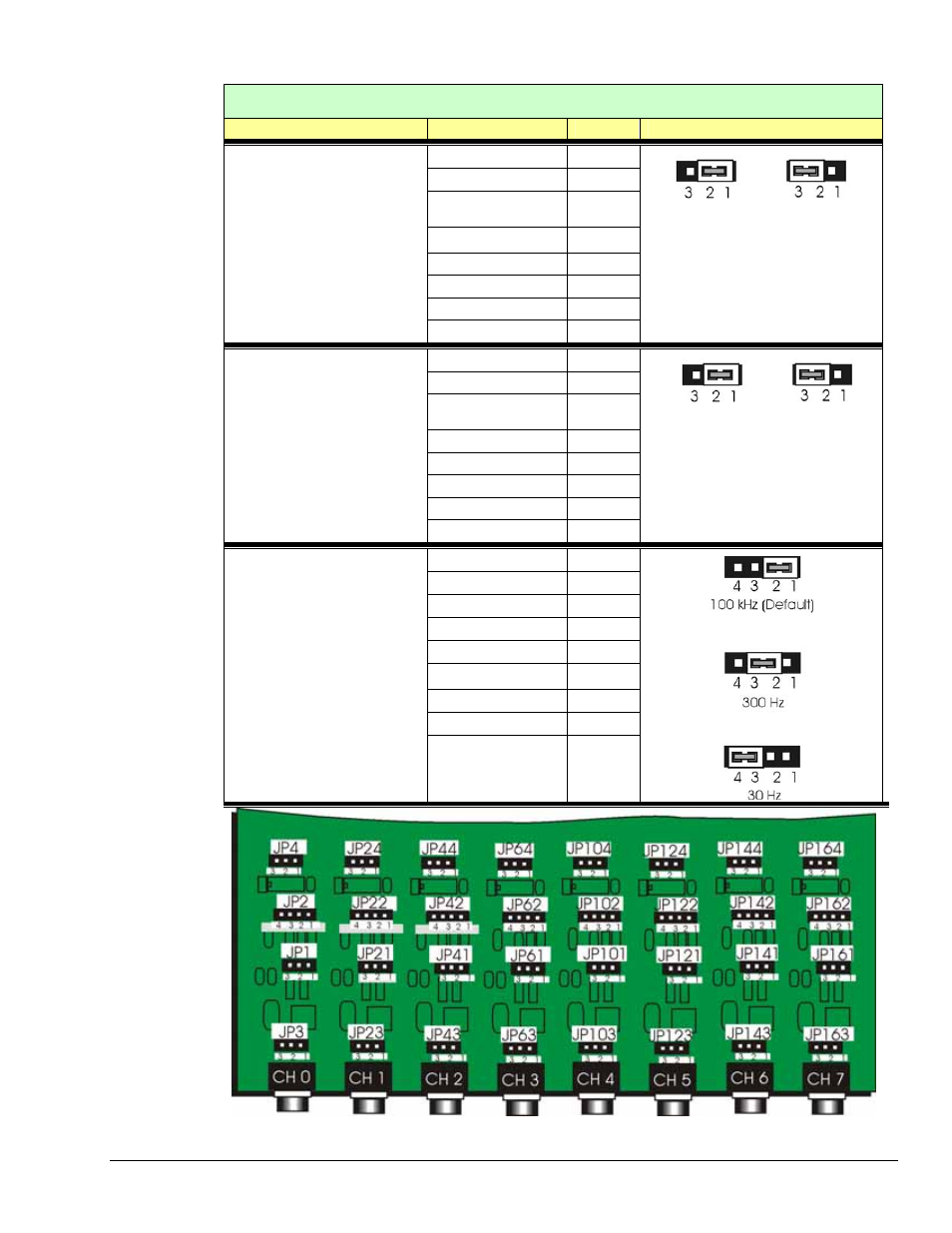
DBK55 On-board Jumper Configurations
Configuration
Jumpers
Channel
Selected Functions
JP3 and JP4 CH 0
JP23 and JP24 CH 1
JP43 and JP44 CH 2
JP63 and JP64 CH 3
Analog
(Default)
Digital
JP103 and JP104 CH 4
JP123 and JP124 CH 5
JP143 and JP144 CH 6
Input Circuit Selection
, pg. 8
•
The default is Analog Input;
Pins 1 and 2 connected for
two associated jumpers.
•
For Digital Input mode; pins
2 and 3 are connected for
the two associated jumpers.
JP163 and JP164 CH 7
* Two jumpers are required to set Analog
or Digital. For example, JP3 and JP4,
which are at the input and output ends of
the circuit, respectively.
JP1 CH
0
JP21 CH
1
JP41 CH
2
JP61 CH
3
JP101 CH
4
JP121 CH
5
JP141 CH
6
Attenuation Selection
, pg. 8
•
The default is Attenuation
Enabled (reduced
sensitivity). Pins 1 and 2
are connected.
•
For Full Sensitivity
(Attenuation Disabled) pins
2 and 3 are connected.
JP161 CH
7
Attenuation
Enabled
(Default)
Full
Sensitivity
JP2 CH
0
JP22 CH
1
JP42 CH
2
JP62 CH
3
JP102 CH
4
JP122 CH
5
JP142 CH
6
JP162 CH
7
Low Pass Filter Selection
, pg. 8
•
The default LPF is 100 kHz.
Pins 1 and 2 are connected.
•
For an LPF of 300 Hz, pins
2 and 3 are connected.
•
For an LPF of 30 Hz, pins 3
and 4 are connected.
Jumper Locations
Partial Board, Not Drawn to Scale
DBK Option Cards and Modules
988793
DBK55, pg. 7