Specifications – dbk85, Reading error vs. source resistance – Measurement Computing DBK Part 2 User Manual
Page 174
Specifications – DBK85
Connectors:
DBK37 male connector designated as P1. Connects to P1 on a DaqBook, DaqBoard, or LogBook via a CA-37-x
or a CA-131-x cable.
BNC: 16 BNC connectors (CH0 through CH15) for signal connection.
Analog Common: Binding Post/Banana Jack. Provides a ground reference point for differential measurements.
Gain Ranges: fixed gain at x1
Inputs: 16 differential voltage inputs
Maximum Voltage Range: ±10 VDC
Input Impedance: 20M Ohm
Accuracy: ±[0.025% +150 µV] (typ), ±[0.1% +250 µV] (max)
Noise: 60 µVrms (typ)
Maximum Input Voltage (without damage): ±25 V
3 dB Bandwidth: 2.6 MHz
CMRR: 80 dB typ
Power: 25 mA max from ±15 VDC
A Note Regarding Source Impedance and Settling Time
High speed multiplexing of signal sources with non-zero impedance will result in reading errors caused by settling
time. In the simplest form, a multiplexing system consists of a group of switches, with internal resistance, and an
output capacitance at the input of an amplifier feeding an A/D converter with a sample-hold circuit on the input.
During the short time a channel signal is connected to the A/D amplifier, the signal must charge the output
capacitance to the true value of the signal so that the sample-hold captures an accurate value for the A/D converter
to digitize. If the source has significant internal impedance the voltage reading will be reduced.
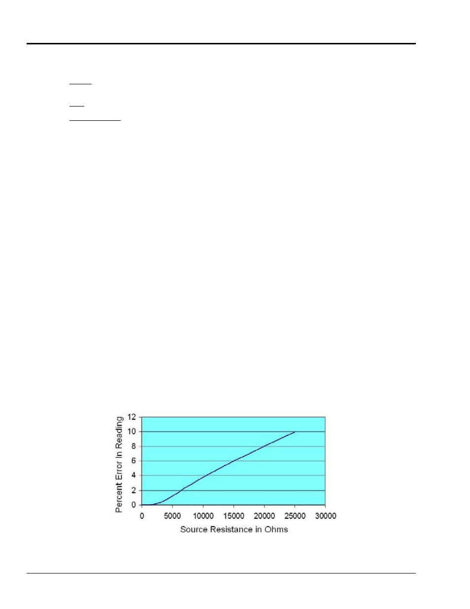
Source impedance below 1000 ohms will create negligible error. Above 1000 ohms, the effects are increasingly
noticeable. An accurate source in series with a variable resistance will readily demonstrate this. Although the
effect is exponential, an easy reference point to remember is that 25K of source impedance will result in
approximately a 10% error.
Reading Error vs. Source Resistance
DBK85 pg. 6
988793
DBK Option Cards and Modules