Connection tips, Caution – Measurement Computing DBK Part 2 User Manual
Page 210
pg. 4, DBK202, DBK203, and DBK204 Series
938994
DBK Option Cards and Modules
Connection Tips
CAUTION
Turn off power to the host PC and externally connected equipment prior to connecting
cables or signal lines to the DBK. Electric shock or damage to equipment can result
even under low-voltage conditions.
Take ESD precautions (packaging, proper handling, grounded wrist strap, etc.)
Use care to avoid touching board surfaces and onboard components. Only handle
boards by their edges (or ORBs, if applicable). Ensure boards do not come into
contact with foreign elements such as oils, water, and industrial particulate.
Do not confuse connectors. Ensure that you only connect P1 I/Os to P1, P2 I/Os to P2,
and P3 I/Os to P3. Improper connection may result in equipment damage.
Be sure to align the P4 orientation indicators () prior to mating the P4 connectors.
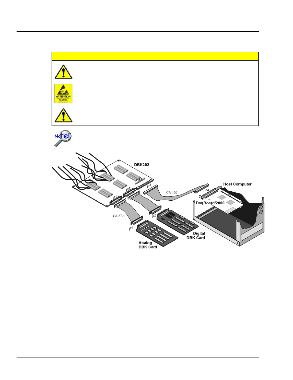
Example of a DBK202 Connected to Analog and Digital DBK Cards via P1 and P2, Respectively
The illustrations and actual board silkscreen are the only references you should need to make proper
connections.
A list of connection tips follows:
1.
Ensure power is removed from the device(s) to be connected.
2.
Observe ESD precautions when handling the board and making connections.
3.
Do not make redundant connections. For example, for ANALOG IN you can use the P1
(DB37) connector or Terminal Blocks TB9 through TB12. You would not use both sets of
ANALOG IN connectors.
4.
There is no need to access the board within a DBK203, DBK203A, DBK204, or DBK204c
unless you need to make connections to P3 or to a terminal block.