Measurement Computing DBK Part 2 User Manual
Page 192
DBK100
Connectors: 2 control connectors allow for daisy
chaining between units and connection to the
DBK101 hub. Each control connector has 9 signals
(power, differential analog input, digital control.)
DBK100/D is terminated in a Deutsch connector for
connecting up to 14 thermocouples via a mating
connector. Though DBK100/D is not shown in the
block diagram, the circuitry is the same as that
indicated. Only the thermocouple connection differs.
DBK100/T accepts 14 industry standard mini-TC
connectors.
Circuitry: The internal circuitry consists of a 16-
channel multiplexor (MUX), differential
instrumentation amplifier with a gain of 100, and
digital control. The units include open thermocouple
detection.
DBK101
Connectors:
The DBK101 hub has 8 connectors
located on the front panel, which link to DBK100 pods
via cable. The rear panel of the DBK101 includes a
P1 connector and an address switch.
Each DBK101 uses up to 8 of P1’s 16 available input
channels. A total of two DBK101 hubs can be
connected to one DaqBook.
Circuitry: The circuitry inside the DBK101 provides
the digital control and analog signal conditioning for
the DBK100 pre-amplifier. The DBK101 contains a
multiplexed pre-charge circuit. A digital control circuit
monitors the addressing of DaqBook’s P1 and
generates serial bit streams for each DBK100 string.
The DBK101 draws all of its power from the
host DaqBook through P1.
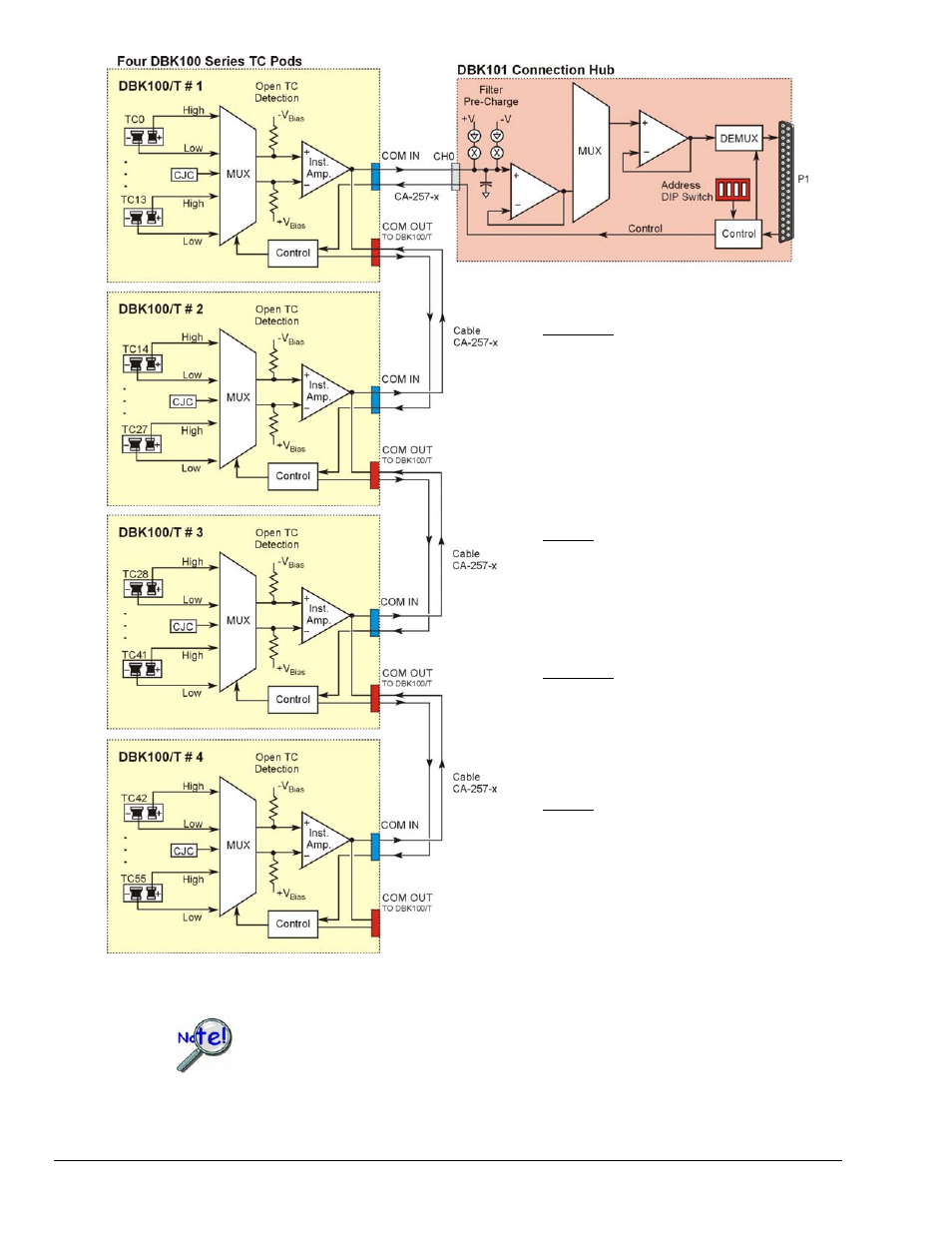
DBK100 / DBK101 System Block Diagram
In comparison to typical DBK options, the DBK101 demands significant power from P1.
It is important that you calculate your system’s power demand, as you may need to add
auxiliary power supplies. For additional information refer to Power Requirements in the
DBK Basics section.
pg. 4, DBK100 Series
907994
DBK Option Cards and Modules