Hardware setup, Input attenuation/gain factors, Signal-to-module connection – Measurement Computing DBK Part 2 User Manual
Page 102: Module configuration
Input Attenuation/Gain Factors
Gain and attenuation may be calculated using the formula:
Input Range
Function
K
300 V Range
Attenuates
60
100 V Range
Attenuates
20
10 V Range
Attenuates
2
1 V Range
Amplifies
0.2
100 mV Range
Amplifies
0.02
Note: not all input ranges are
available on a single unit.
K = Vin / Vout
where: K is the attenuation or gain factor (the values of K for
available voltage ranges are given in the table).
Vin is the voltage applied to the module input channel.
Vout is the amplified or attenuated voltage from the module
output back to the main unit.
Hardware Setup
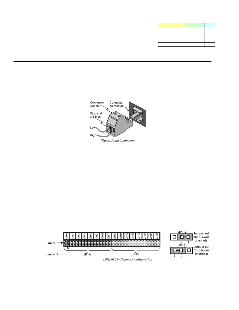
Signal-to-Module Connection
The DBK50/51 rear panel has 8 plug-in screw terminals for easy access to the 8 analog input channels.
There is a high (right side) and a low (left side) terminal in each pair to maintain consistent polarity (see
figure). For AC signals, the polarity is arbitrary unless multiple signals must maintain their phase
relationship.
Module Configuration
Factory Default: Low-pass filter – Enabled
Several jumpers must be set on the DBK50 and DBK51 to match your application:
•
2 jumpers on JP1A or JP1B to select the main channel to use (see following figure).
•
1 jumper on JP1C for upper or lower sub channels
•
1 jumper on JPn02 to use or bypass the low-pass filter—one for each channel number (n)
The main output channel is one of the 16 primary data acquisition device [LogBook or Daq device]
channels. Each DBK50 [and DBK51] has 8 input channels and can be set to an upper or lower sub-
channel that allows 2 modules to share a single LogBook or Daq device channel. Thus, a fully-populated
system can have 256 input channels.
After determining a main channel number for the module, set two jumpers on JP1A or JP1B for the desired
channel. The two jumpers must be used side-by-side on the selected channel. This is illustrated for
channel 0 in the following figure. Next, set the JP1C jumper for the eight upper or eight lower sub-
channels. Note that two modules may share the same main channel if one is set to the upper sub channel
and the other set to the lower sub channel.
Each of the 8 input channels has a 3-pole low-pass filter that may be manually selected or bypassed by
positioning 2 shunt jumpers on 2×2 headers for each channel. Orient the jumpers parallel/horizontal
(enable) or perpendicular/vertical (bypass) to the header label (JP102 to JP802 for each of 8 channels).
The following figure can be used for orientation.
DBK50 and DBK51, pg. 2
989594
DBK Option Cards and Modules