Measurement Computing DBK Part 2 User Manual
Page 198
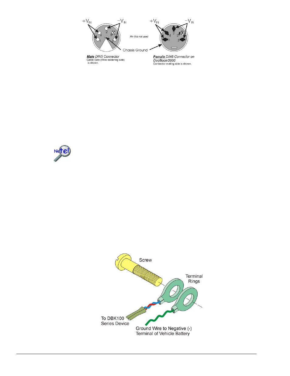
The lines that will connect to the vehicle battery are soldered to the male DIN5 connector. As indicated in
the first figure on this page, the +V
IN
line connects to the battery’s positive (+) terminal and should have a
7.5 amp fuse in series with the line. The -V
IN
and Chassis Ground lines both connect to the battery’s
negative terminal.
Shielding
Using shielded TC wire with the shield connected to analog common [DBK101 ACOM jack] will result in
further noise reduction. Using a shielded ribbon cable to connect the DBK101 male P1 connector to the P1
connector of the primary data acquisition device (DaqBoard/2000) will also help minimize noise.
CA-143-7 and CA-143-18 are female-to-female, DB37 shielded ribbon cables of 7-inch and 18-inch
lengths, respectively.
If a thermocouple shield is connected to a DBK101 module, leave the shield unconnected
at the other end of the thermocouple. Connecting the shield to common at both ends will
result in a ground loop.
TC Common Mode
The maximum common-mode voltage for the DBK100 is ±5 volts. Common-mode voltage is the DC or
AC voltage signal that is applied equally to both sides of a differential input.
If a thermocouple is connected directly to a component in the vehicle at a potential that is over the
maximum common-mode voltage, then very noisy or incorrect readings will be seen. Thermocouple
connections that are made directly to the alternator or engine block may also result in high noise. Two
methods of reducing noise are:
(a)
Run a ground line from the bolt, as indicated in the first figure.
(b)
Isolate the thermocouple leads with a set of washers, one of which is mica.
This is indicated in the second figure.
Running a Ground Wire to the Battery’s Negative Terminal
pg. 10, DBK100 Series
907994
DBK Option Cards and Modules