Creating a 4 to 20ma current loop, Warning – Measurement Computing DBK Part 2 User Manual
Page 133
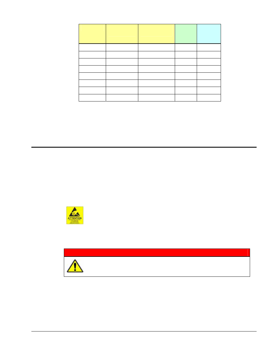
Channel
PGM Resistor
Location
Voltage Out
Jumper Header
Voltage
Set
V
out
Resistor
Value
R
2
CH00 R110
J11
CH01 R120
J21
CH02 R130
J31
CH03 R140
J41
CH04 R150
J51
CH05 R160
J61
CH06 R170
J71
CH07 R180
J81
6.
On the jumper header, reposition the channel’s voltage out jumper to the “PGM” position. Refer to
the table for a channel’s applicable Jumper Header. The header numbers appear on the circuit board.
7.
If applicable, install resistors for other channels, and set the applicable voltage out jumper headers to
PGM.
8.
Re-install the top cover plate and secure it with the 4 screws that were removed in step 3.
Creating a 4 to 20mA Current Loop
Inputs to monitor the commonly used 4 to 20mA current loops most often employ a 250
Ω precision
resistor to develop a 1 to 5 VDC voltage drop.
Ideally, a resistor for such purpose should have a 0.1% tolerance (or better) with a minimum power rating
of 0.25W and a temperature coefficient of at least 25ppm/°C.
Lower values of resistance, for example, 62.5
Ω [for a lower voltage drop within the loop of 0.25 to 1.25
VDC] will require that the host data acquisition device use a gain of x4 to maximize the signal resolution.
The discharge of static electricity can damage some electronic components.
Semiconductor devices are especially susceptible to ESD damage. You should
always handle components carefully, and you should never touch connector pins or
circuit components unless you are following ESD guidelines in an appropriate ESD-
controlled area. Such guidelines include the use of properly grounded mats and
wrist straps, ESD bags and cartons, and related procedures.
WARNING
HOT COMPONENTS! Allow the DBK65 module to cool for at least 30 minutes
before removing the top cover. Some internal components can become very hot
and may cause burns.
To create a 4 to 20mA current loop:
1.
Remove the DBK65 from power and disconnect all signal lines.
2.
Allow the unit to cool for at least 30 minutes.
3.
Remove the 4 screws from the top cover plate. Then remove the plate.
4.
Remove solder from the 2 holes at the resistor mounting location (see the following figure for
location).
DBK Option Cards and Modules
988793
DBK65 pg. 5