Customizing a voltage, Warning – Measurement Computing DBK Part 2 User Manual
Page 132
Customizing a Voltage
To make use of the custom voltage feature you will need to acquire a resistor of the calculated value. The
formula to use is:
R
2
= (V
out
– 1.2V) / 0.007645
Example:
Suppose you wanted an excitation source of 12V. Simply replace the V
out
variable with 12V and solve for
R
2
. Thus, R
2
= (12 - 1.2) / 0.007645 = 1412.688
Ω Ιn practice, a 1400 ohm, 1% resistor would be used.
Of course, 1400
Ω is a little off from the 1412.688Ω, which was calculated. To see the actual nominal
voltage that would result from 1400
Ω we can use a second equation.
V
out
= 1.2V (1 + R
2
/158) + 0.00005*R
2
V
out
= 1.2 (1 + 1400/158) + 0.00005*1400 = 11.903 volts
After the resistor value is known, it can be installed as follows.
The discharge of static electricity can damage some electronic components.
Semiconductor devices are especially susceptible to ESD damage. You should
always handle components carefully, and you should never touch connector pins or
circuit components unless you are following ESD guidelines in an appropriate ESD-
controlled area. Such guidelines include the use of properly grounded mats and
wrist straps, ESD bags and cartons, and related procedures.
WARNING
HOT COMPONENTS! Allow the DBK65 module to cool for at least 30 minutes
before removing the top cover. Some internal components can become very hot
and may cause burns.
1.
Remove the DBK65 from power and disconnect all
signal lines.
2.
Allow the unit to cool for at least 30 minutes.
3.
Remove the 4 screws from the top cover plate. Then
remove the plate.
4.
Remove solder from the 2 holes at the resistor mounting
location.
5.
Using rosin core solder and proper soldering technique,
solder the resistor into position for the applicable
channel.
Be sure that the resistor leads are short
enough to avoid making contact with the metal
chassis
.
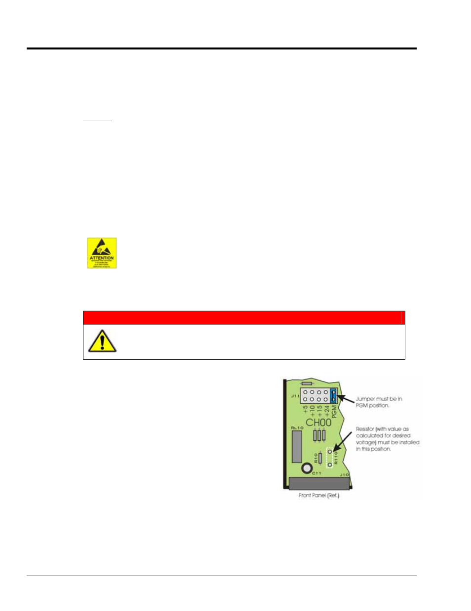
The figure to the right indicates the resistor location for
use with channel 0 (CH00). The location scenario is similar
for all 8 channels.
Refer to the following table for a channel’s PGM Resistor Location
number. The location numbers appear on the circuit board.
DBK65 pg. 4
988793
DBK Option Cards and Modules