Measurement Computing DBK Part 2 User Manual
Page 67
Note: A series of interface cables are available to connect up to 128 DBK44s. You can also use a DBK41
10-slot expansion chassis.
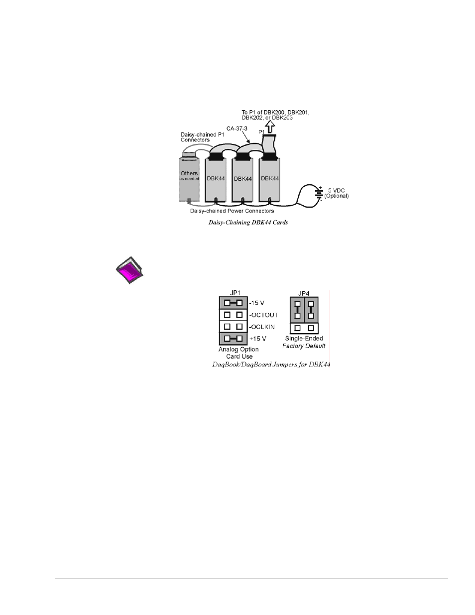
DBK44 can be connected to the P1 connector of DBK200, DBK201, DBK202, or DBK203. Connect the
CA-37-x accessory ribbon cable (with x indicating the number of cards to be connected) from P1 to the
DB37 connector at the end of the DBK44 card.
Note: Interface cables are available to connect up to 128 DBK44s.
CE Compliance
Reference Notes:
Should your data acquisition system need to comply with CE standards, refer to
the CE Compliance section of the chapter
Signal Management
.
DaqBook/100 Series & /200 Series and DaqBoard [ISA type] Configuration
The DBK44 requires two setup steps in DaqBooks/100 Series & /200 Series devices and
DaqBoards [ISA type]—jumpers JP1 and JP4.
1.
If not using auxiliary power, ensure the JP1 jumper is configured for Analog Option Card Use
(expanded analog mode).
Note: This default position is necessary to power the interface circuitry of the DBK44 via the
internal ±15 VDC power supply. If using auxiliary power from a DBK32A or DBK33 card,
you must remove both JP1 jumpers. Refer to Power Requirements in the DBK Basics section.
Also refer to the DBK32A and DBK33 sections as applicable.
2.
For DaqBook/100, /112, and /120 only, place the JP4 jumper in the DaqBook or DaqBoard [ISA
type] in single-ended mode. Note that analog expansion cards convert all input signals to single-
ended voltages referenced to analog common.
Note: The configuration of the JP3 jumper depends on the output range of the 5B module. For
example, a 5B31 volt input module has an output range of -5 to +5 V in bipolar mode. A
5B47 T/C module (output 0 to +5 V) could use bipolar mode, but unipolar mode is more
appropriate.
DBK Option Cards and Modules
877095
DBK44, pg. 5