Using the screw-terminal blocks – Measurement Computing DBK Part 2 User Manual
Page 266
DBK213, pg. 6
969294
DBK Option Cards and Modules
Using the Screw-Terminal Blocks
You must remove the DBK213 module’s cover plate to access the screw terminal blocks. This is described in steps
1 and 2 below.
1.
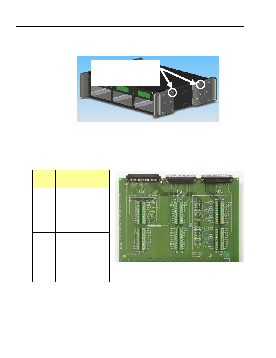
Remove the top inward screws from each of the 4 mounting brackets. See following figure.
The Cover Plate is Secured by 4 Srews
[2 Screws per-side]
To remove the cover plate you
must first remove the top
inward screw from each of the
4 mounting brackets.
2.
After the 4 screws have been removed, carefully remove the cover plate.
3.
Make the wiring connections to the terminals. Refer to the board’s silkscreen and to
the pin correlations on the next few pages.
In general, the following terminal block-to-signal relationships apply:
DBK213
Terminal
Blocks
Used for . . .
Alternative
TB9
TB10
TB11
TB12
ANALOG I/O
P1 or P4*
TB5
TB6
TB7
TB8
DIGITAL I/O
P2 or P4*
TB1
TB2
TB3
TB4
PULSE/
FREQUENCY/
DIGITAL I/O
P3 or P4*
DBK213 Board
Note that the P3 DB37 Connector and its associated board cable
has been removed for clarity.
*
P4 is used for connecting to DaqBoard/2000 Series devices.
4.
Tighten the terminal block screws snug; but do not over-tighten.
5.
After all terminal connections are made and verified correct, return the cover to the unit and
secure in place with the 4 screws removed earlier. Tighten snug, but do not over-tighten.
The following pages correlate the DBK213 terminal block connectors with the associated pins of
the P1, P2, and P3 DB37 connectors. Note that the System Connections and Pinouts chapter
contains additional pin-outs, and includes references to the 100-pin P4 connector.