Screw-terminal adapter board, Screw-terminal adapter modules – Measurement Computing DBK Part 2 User Manual
Page 209
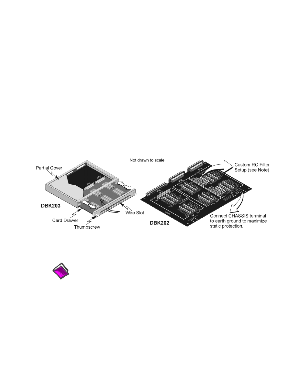
Screw-Terminal Adapter Board
The DBK202 Board provides a means of connecting channel input signals to a /2000 Series device through
one of three methods:
•
With cables connected to P1, P2, and P3 connectors, as applicable.
•
With signal wires connected to the appropriate screw-terminal blocks (TB1 through TB12).
Note that the DBK202 board’s silkscreen clearly identifies all screw terminals.
•
With a combination of the above two methods.
When connecting a DBK202 to a P4 connector, a CA-195 cable is used. The cable has a P4 connector
located at each end.
Note: DBK202 contains mounting holes that allow the board to be secured inside a user-provided
enclosure.
Screw-Terminal Adapter Modules
The DBK203, DBK203A, DBK204, and DBK204c each consist of a DBK202 board housed in a chassis.
The DBK203 [and DBK204 and DBK204c units that use it] include a card drawer that can be slid free of
the module. The sliding card drawer provides easy access to the twelve terminal blocks and to the 40-pin
P3 header. The DBK203A (which supersedes the DBK203) and the DBK204 and DBK204c units which
use the DBK203A have no slide out drawer.
DBK203 Includes a Slide-Out DBK202 Board
DBK203A has no Slide-Out Option
Reference Note for Custom RC Filter Setup:
You can install resistors and capacitors to create RC networks for P1 Analog Input Channels.
For detailed information, refer to Adding Resistor/Capacitor Filter Networks, which begins on
page 12 of this DBK section.
DBK Option Cards and Modules
938994
DBK202, DBK203, and DBK204 Series, pg. 3