Hardware setup, Module connection – Measurement Computing DBK Part 2 User Manual
Page 162
In comparison to typical DBK options, the DBK84 demands significant power from the
system’s
±15 V power supplies. It is important that you calculate your system’s power
demand, as you may need to add auxiliary power supplies. For additional information
refer to Power Requirements in the DBK Basics section.
Hardware Setup
Module Connection
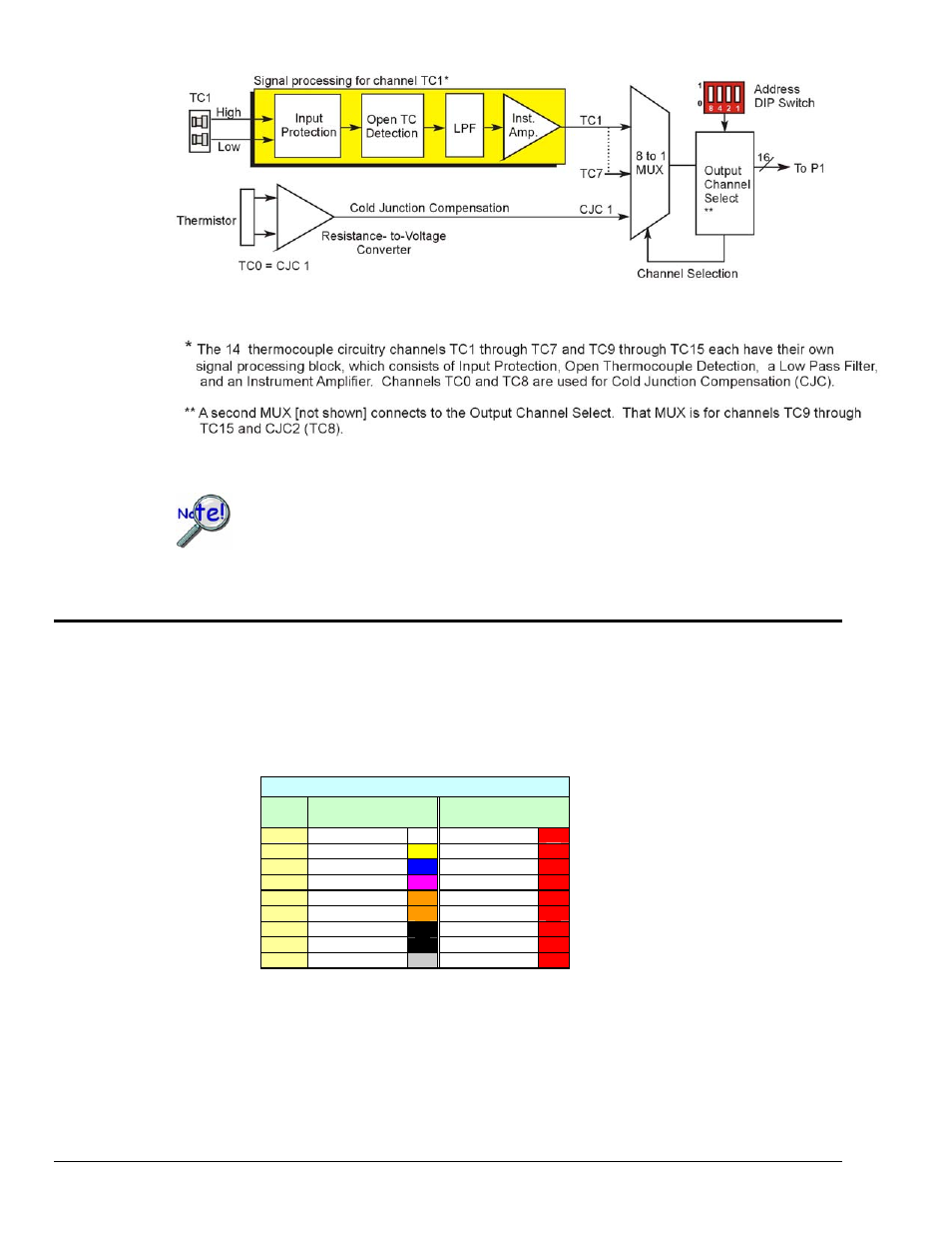
The DBK84 accepts up to 14 mini-TC plugs in its channels 1 through 7 and 9 through 15. All channels
have the same level of functionality.
Thermocouple wire is standardized, color-coded, and polarized, as noted in the following table.
Thermocouple Standards
T/C
Type
(+) Lead to
Channel High
(-) Lead to
Channel Low
J White Red
K Yellow Red
T Blue Red
E Violet Red
N28 Orange Red
N14 Orange Red
S Black
Red
R Black
Red
B Gray Red
Mini-TC plugs are type-specific, and for best measurement operation the plug TC type should match the
wire TC type. If necessary, copper/copper (Type U) plugs may be used, but measurement stability will be
slightly degraded. Mini-TC plugs are polarized as well, and it is critical for proper measurement operation
that this polarity be followed when connecting the thermocouple wire. Once wired, the TC plugs will only
mate into the DBK84’s connectors in one orientation, ensuring a correct connection.
It should be noted that thermocouples output very small voltages and that long thermocouple leads can
pickup a large amount of noise. However, the DBK84 inherently provides a high level of noise immunity
via its 4 Hz signal bandwidth and input filtering. If desired, further noise reduction can be achieved
pg. 2, DBK84
989494
DBK Option Cards and Modules