Measurement Computing DBK Part 2 User Manual
Page 43
DBK Option Cards and Module
899892
DBK43A & DBK43B, pg. 23
6. Select the type of calibration to be performed, i.e., Nameplate, Two-Point, or Shunt. Then
edit the Application Parameters, if applicable. A brief description of the three calibration
methods follows. When done, click the
• Nameplate calibration provides a way to enter parameters for your strain gage
and its application. The final step of the procedure includes attaching the strain
gage (load cell).
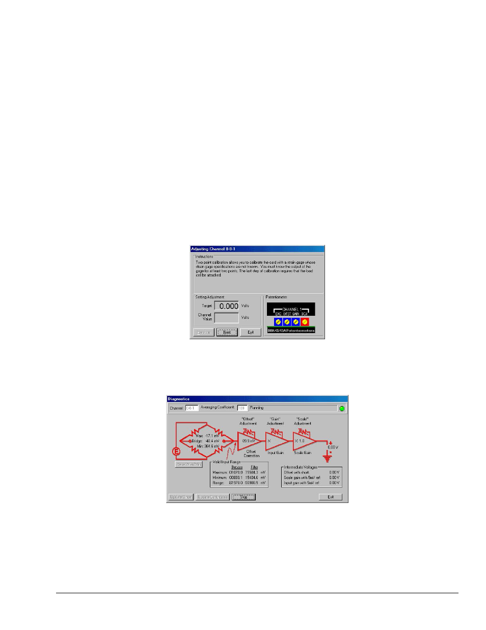
• Two-Point calibration provides a way to calibrate a DBK16, DBK43,
DBK43A, or DBK43B that is using a strain gage with unknown specifications.
In this method, the user enters two points of transducer output [milli-volts] vs.
engineering units, e.g., pounds. GageCal provides set up instructions based on
the parameters entered. The final step of the procedure includes attaching the
strain gage (load cell).
• Shunt calibration provides a means calibrating channels with use of user-
supplied shunts to simulate a physical load. With this method, 1 or 2 shunt
resistors (Rn00D and Rn00H) are added for each of the 8 channels to be
calibrated. You must set J3 to the position closest to TP9 for the shunt
calibration to work correctly. Shunt calibration is performed with the load-cell
attached.
7. Follow GageCal’s screen prompts to complete the calibration.
Example Screen Shot from GageCal
Note
: You can use GageCal’s “Diagnostics” feature to view a graphic representation
of the strain gage and the card’s gain stages.
GageCal Diagnostics
8. After completion, go to DaqView and convert
±5 V to engineering units using mx+b.