Installing dbk cards – Measurement Computing DBK Part 2 User Manual
Page 263
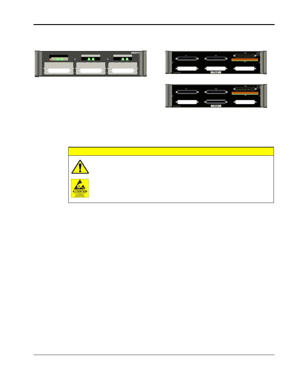
Installing DBK Cards
Front Panel with 3 Vacant Card Slots
P1 P2 P3
Rear Panel View with No Card Installed
Beneath
P3
Beneath
P2
Beneath
P1
Rear Panel View with
Card Installed in Slot 2 Beneath P2
The DBK213 has three card slots which allow for the easy installation of DBK cards. To install a card
observe the following CAUTION and then complete the few simple steps.
CAUTION
Turn off power to the host PC and externally connected equipment prior to connecting
cables or signal lines to DBKs. Electric shock or damage to equipment can result even
under low-voltage conditions.
Take ESD precautions (packaging, proper handling, grounded wrist strap, etc.)
Use care to avoid touching board surfaces and onboard components. Only handle
boards by their edges (or ORBs, if applicable). Ensure boards do not come into
contact with foreign elements such as oils, water, and industrial particulate.
1.
Refer to your specific DBK card instructions prior to installing the card. You may need to make
physical hardware configurations, for example, regarding channel assignments.
2.
Complete all DBK card configuration per your application and channel assignment needs.
3.
Make signal line connections on your DBK card as applicable. Screw-terminal connections and BNC
connections are typical.
4.
If hex nuts are present on your DBK card’s DB37 connector, remove them and put them aside for
reuse in step 7.
5.
Using the lower card-edge-guide on the DBK213 front panel [and possibly the upper guide for high
cards such as the DBK82], carefully slide the card into the desired slot such that the card’s DB37
connector goes to the rear panel of the DBK213. The following should be considered when choosing
a card slot.
o
Analog I/O cards will connect to the DBK213’s P1 male DB37 connector.
o
Digital I/O cards will connect to the DBK213’s P2 male DB37 connector.
o
Pulse/Frequency (Digital and Counter/Timer) I/O will connect to the DBK213’s P3
male DB37 connector.
6.
Push the DBK card until its DB37 connector extends through the rear panel of the DBK213.
7.
Using the hex nuts removed in step 4 (or replacement hex nuts if needed), secure the card at the rear
panel. Tighten the hex nuts snug, but do not over tighten.
8.
Repeat these steps for each remaining card.
DBK Option Cards and Modules
969294
DBK213, pg. 3