Hardware setup, Card connection caution, Card configuration – Measurement Computing DBK Part 2 User Manual
Page 72
DBK45 Block Diagram
Hardware Setup
Card Connection
CAUTION
Input voltage levels must not exceed ±5 V bipolar or 10 V unipolar.
DBK45 is equipped with a BNC connector for each of the four differential analog inputs. The card
includes terminal block connections, which can be used instead of the BNC connectors if desired.
Card Configuration
Factory Defaults:
•
100K bias resistors – Enabled
•
Low pass filter – Disabled (bypassed)
•
Gain – x1
•
SSH - Enabled
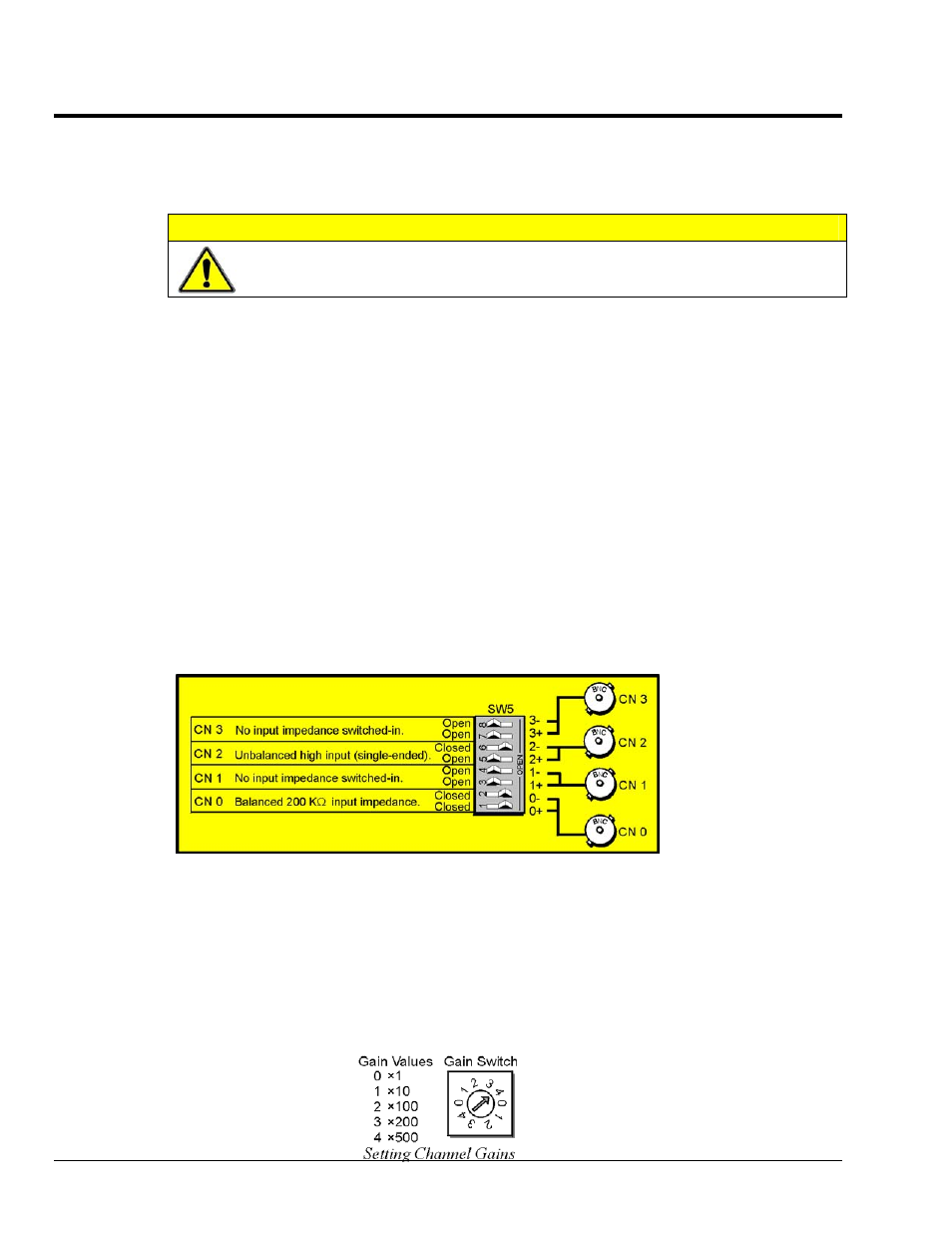
Input Termination
DBK45 provides two 100 K
Ω bias resistors for each analog input. For balanced 200 KΩ input
impedance, both resistors should be switched in. An 8-position DIP switch (SW5) can selectively engage
the bias resistors. The switches must be in the closed position to engage the termination resistors. For
unbalanced high input, only the (-) resistor should be used. If neither resistor is used, some external bias
current path is required. Examples of SW5 switch positions and the resulting impedance selection
follows.
Examples of Bias Resistor Selection Options
Gain Settings
On the printed circuit board, each channel has one gain-set switch. The switches are labeled GAIN 1,
GAIN 2, GAIN3, and GAIN 4. Each channel also has holes in the board for gain resistors labeled RG1 to
RG4. The 5 gain values for switch settings 0 to 4 are provided in the following figure. If a custom gain is
desired, the switch is set to position 0; and a gain resistor must be mounted and soldered onto the board.
The gain resistor’s value is determined by the formula: R
GAIN
= [40,000 / (Gain -1)] - 50
Ω
DBK45, pg. 2
987696
DBK Option Cards and Modules