Adding resistor/capacitor filter networks, Warning, Caution – Measurement Computing DBK Part 2 User Manual
Page 301
Adding Resistor/Capacitor Filter Networks
WARNING
Disconnect the DBK215 from power and signal sources prior to installing capacitors or
resistors.
CAUTION
Ensure wire strands do not short power supply connections to any terminal potential.
Failure to do so could result in damage to equipment.
Do not exceed maximum allowable inputs (as listed in product specifications). There
should never be more than 30 V with reference to analog ground (AGND) or earth
ground.
You must provide strain-relief (lead slack) to all leads leaving the module. Use tie-wraps
[not included] to secure strain-relief.
Always connect the CHASSIS terminal to earth ground. This will maximize static
protection.
If a channel is not associated with a DBK expansion option you can install a customized RC filter network
to improve the signal-to noise ratio, assuming that an unacceptable level of noise exists. DBK215’s
internal board includes silk-screened sockets for installing RC filter networks. The following table
contains values that are typical for RC filter network components.
Typical One-Pole Low Pass Filter
Values
for DBK215
R
C
f
f
Ohms µF Hertz
(-3dB)
kHz
(-3dB)
510 1
312
0.31
510 0.47 664
0.66
510 0.22
1419
1.42
510 0.1
3122
3.12
510 0.047 6643 6.64
510 0.022
14192
14.19
510 0.01
31223
31.22
510 0.0047 66431 66.43
470 0.0033
102666
102.67
Do not use RC filters in conjunction with additional DBK expansion
accessories.
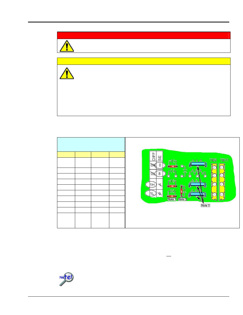
An Example of Customer-Installed
Capacitors and Filters for RC Networks
In this example Channels 0 and 8 are shown as Single-Ended.
Channel 1 is Differential, i.e., using 1H and 1L (channel High and Low).
The following three notes pertain to the above figure.
Note 1: The 3 horizontal capacitors [as oriented in the illustration] are optional filter capacitors.
Note 2: The vertical capacitor [as oriented in the illustration] is an optional isolation capacitor used for the
reduction of Differential noise. Such capacitor placement is not used in Single-Ended applications.
Note 3: If installing filter resistors, carefully drill out the indicated centers with a 1/16 inch drill-bit. Otherwise
the resistor will be short-circuited.
Prior to installing RC components, review the previous Warning and Caution
statements, then read over the following information regarding resistors and
capacitors.
DBK Option Cards and Modules
897994
DBK215 pg. 11