Measurement Computing DBK Part 2 User Manual
Page 73
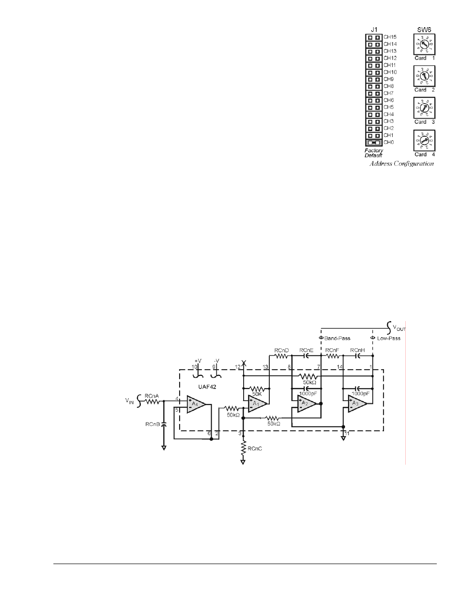
Address Configuration
Up to four DBK45s can be connected to each analog channel. With
16 main channels and 4 inputs per DBK45, 256 inputs are possible. Since this is
a daisy-chain interface, each DBK45 must have a unique address (channel and
card number). Note that the default setting of SW6 is Card 1.
To configure the module, locate the 16 × 2-pin header (labeled J1) near the front
of the board (near P1). The 16 jumper locations on this header are labeled CH0
through CH15. Place the jumper on the channel you wish to use. Only one
jumper is used.
Note: Two DBK45s in the daisy-chain can have the same channel number as
long as their card number is unique.
Set switch SW6 for each DBK45 on a single channel. Verify that only one card
in the system is set to a particular channel and card number.
Configuring DBK45 Filter Sections
There are 4 low-pass, 3-pole active filters on the DBK45. Each filter can be enabled (EN) or bypassed
(BY) by placement of the jumper on J3 for channel 0, J4 for channel 1, J5 for channel 2, J6 for
channel 3. The factory-default setting is enabled (EN) for each channel. Each filter can be configured as
a Butterworth, Bessel, or Chebyshev filter with corner frequencies up to 50 kHz. Filter properties depend
on the values of resistors and capacitors installed in several circuit locations. Above 10 Hz, installing
capacitors is unnecessary because capacitors in the ICs are sufficient. In all cases, three resistors are
required to complete the active filter circuits contained mostly within the UAF42 ICs.
The following circuit diagram shows the active filter IC in a typical section of the DBK45. The resistors
and capacitors outside the IC have a physical location in a DIP-16 socket (dual in-line, 16 pins) with an
RCnn designator. The RC indicates the needed part is a resistor or capacitor; the 3rd character is the
channel number; and the 4th character corresponds to the socket position (A-H).
Filter Circuit Diagram
A machined-pin IC socket in each filter RC location can accept resistors and capacitors that plug directly
into the socket; however, this is not recommended. Two much better approaches exist. The first is to use
pre-configured plug-in filter modules; the second is to configure your own plug-in module using a blank
CN-115. Both of these options are illustrated on the following page.
The use of plug-in modules provides excellent “gold-to-gold” contact between the components of the plug-
in module and the on-board header.
DBK Option Cards and Modules
987696
DBK45, pg. 3