Channel calibration procedure – Measurement Computing DBK Part 2 User Manual
Page 53
DBK Option Cards and Module
899892
DBK43A & DBK43B, pg. 33
Channel Calibration Procedure
Adjust the Offset
The following steps are used to adjust the offset.
1. In the Param1 column (see page 29 for location), select all of the DBK43A channels that are
to be adjusted.
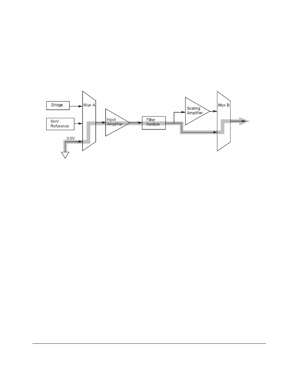
2. Select Mode = SetOffset from the drop down list above the grid. This selection commands
the calibration multiplexer to route the 0.0V reference through the entire analog path (see
following figure).
“Mode = Offset” 0.0 Volt Reference is Routed
3. Turn off all the channels in the system except for those DBK43A channels that are to be
adjusted.
4. Click the Download button. This sends the current configuration to the LogBook.
5. Select Indicators \ Enable Input Reading Column from the menu bar. This displays the offset
values for the enabled channels.
6. Set the offset voltage to 0.0V for each transducer by adjusting the trimpot labeled OFFSET
for the associated channel.
7. Select Indicators \ Disable Input Reading Column from the menu bar.
Adjust the Input Amplifier Gain
Perform the following steps to adjust the Input Amplifier Gain.
1. In the Param1 column (see page 27 for location), select all of the DBK43A channels that are
to be adjusted.
2. Select Mode = SetInputGain from the drop down list above the grid. This selection
commands the calibration multiplexer to route a 5mV reference through the Input Amplifier
and bypass the Scaling amplifier (see following figure).
Note:
If the filter is enabled (not bypassed) accommodate an additional x2 gain stage.