Adding resistor/capacitor filter networks – Measurement Computing DBK Part 2 User Manual
Page 218
pg. 12, DBK202, DBK203, and DBK204 Series
938994
DBK Option Cards and Modules
Adding Resistor/Capacitor Filter Networks
WARNING
Disconnect the DBK202, DBK203, DBK203A, DBK204, or DBK204c from power and
from signal sources prior to installing capacitors or resistors.
CAUTION
Ensure wire strands do not short power supply connections (+15 V, -15 V, +5 V, etc.) to
any terminal potential. Failure to do so could result in damage to DaqBook/2000 Series
devices, DaqBoard/2000 Series boards, or DaqBoard/2000c Series boards.
Do not exceed maximum allowable inputs (as listed in product specifications). There
should never be more than 30 V with reference to analog ground (AGND) or earth
ground.
Do not operate DBK202 on an exposed metal surface.
You must provide strain-relief (lead slack) to all leads leaving DBK202, /203, /203A,
/204, or /204c. Use tie-wraps [not included] to secure strain-relief.
Always connect the CHASSIS terminal to earth ground. This will maximize static
protection.
You can install customized RC filter networks to improve the signal-to noise ratio when an unacceptable
level of noise exists. DBK202, /203, /203A, /204, and /204c include sockets for installing RC filter
networks directly on the board.
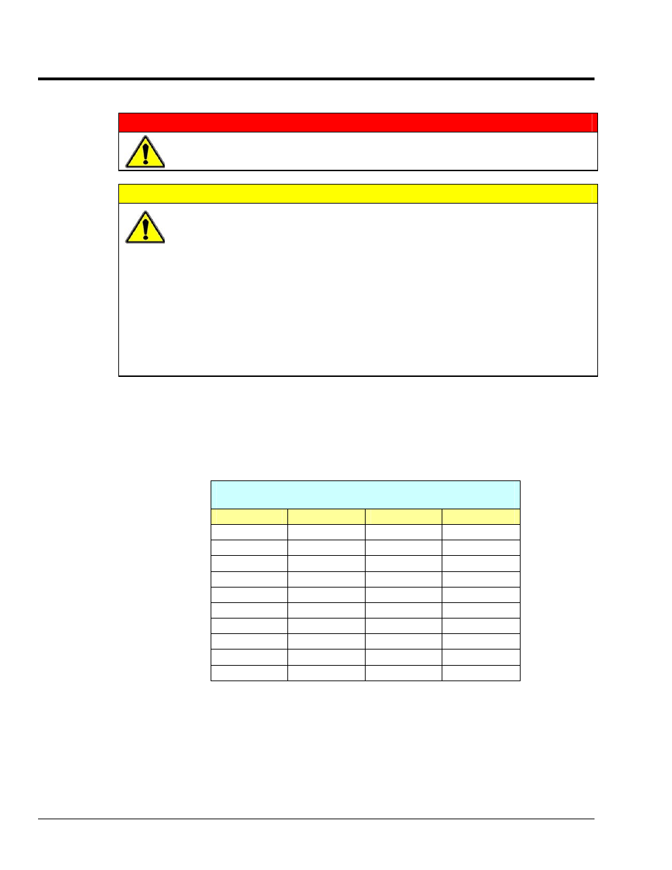
The following table contains values that are typical for RC filter network components.
Typical One-Pole Low Pass Filter Values
for DBK202, DBK203, DBK203A, DBK204, and DBK204c
R
C
f
f
Ohms
µF
Hertz (-3dB)
kHz (-3dB)
510 1
312
0.31
510 0.47
664
0.66
510 0.22
1419
1.42
510 0.1
3122
3.12
510 0.047
6643
6.64
510 0.022
14192
14.19
510 0.01
31223
31.22
510 0.0047
66431
66.43
470 0.0033
102666
102.67