Measurement Computing DBK Part 2 User Manual
Page 244
DBK208, pg. 8
987594
DBK Option Cards and Modules
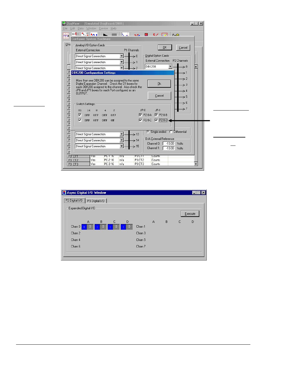
Configure System Hardware and DBK208 Configuration Settings Windows
Switch Settings
The switch settings must
agree with those on the
actual DBK208 board.
Refer to pages 5 and 6 of
this section for configu-
ration details.
For Digital Output
Ensure the JP0 and JP1
boxes are checked for each
port configured as Digital
Output.
For Digital Input
Ensure the JP0 and JP1
boxes are not checked for
each port configured as
Digital Input.
Async Digital I/O Window – P2 Digital I/O Tab Selected
In the above screen shot of the Digital I/O Window, channel 0 represents two DBK208 boards. The
first board consists of banks A and B, the second board consists of banks C and D. In this example all
four banks are seen as Input. The input determination was made by the physical positions of hardware
jumpers (JP0 and JP1) and software selections for JP-0 and JP-1, i.e., that for Digital Input they were
not checked.
Note: When Output is selected, hexadecimal values must be entered in the “O” block for the
applicable bank.
8.
Upon completion of the configuration click the Execute button.