Configuring the primary data acquisition device – Measurement Computing DBK Part 2 User Manual
Page 171
Configuring the Primary Data Acquisition Device
DaqBook/100 Series & /200 Series and DaqBoard [ISA type] Configuration
Use of a DBK85 with a DaqBook/100 Series, /200 Series devices, or with an ISA-type DaqBoard requires
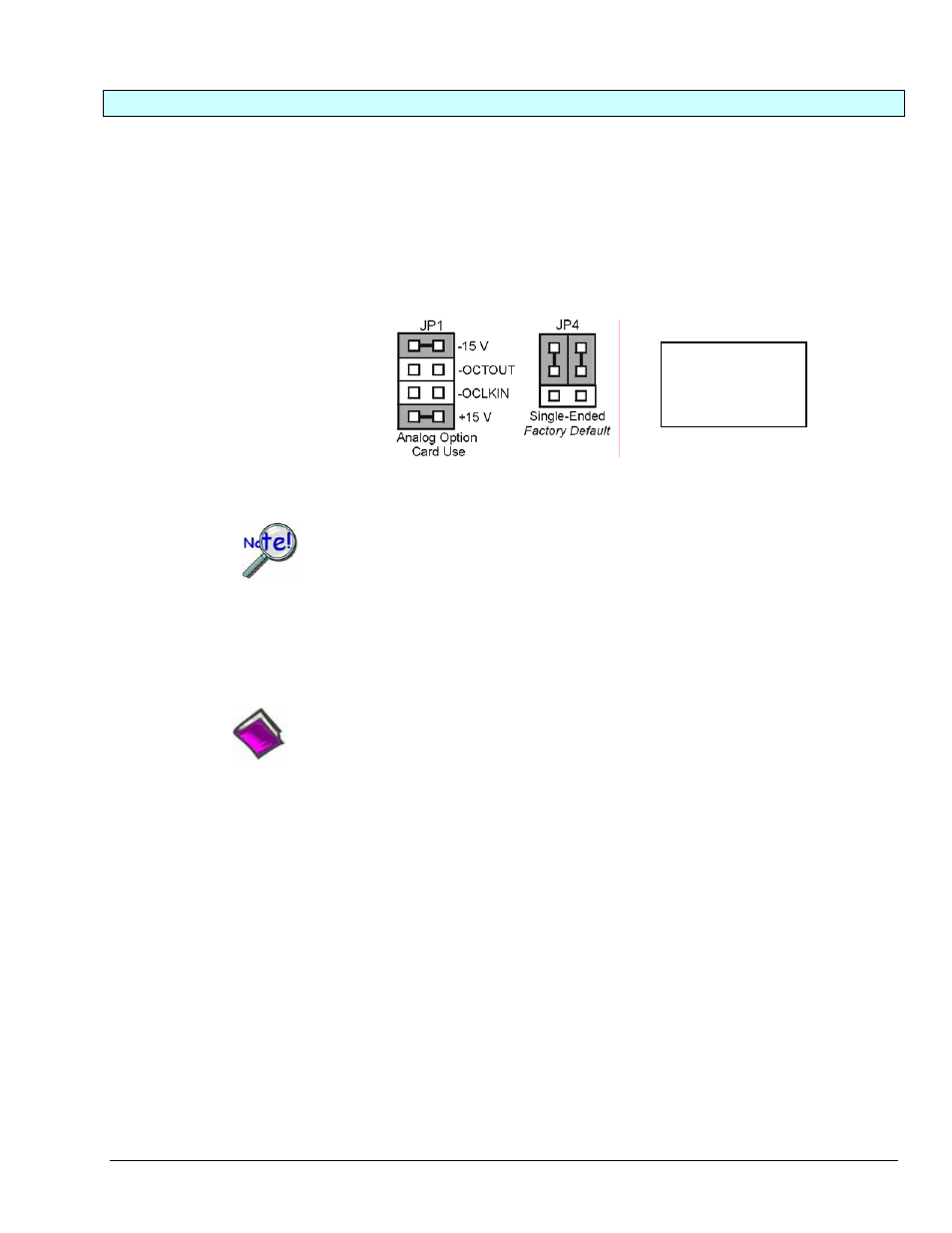
the configuration of jumpers JP1 and JP4. These jumpers are located on the DaqBook/100 Series, /200
Series devices, and DaqBoard [ISA type] board.
1.
If not using auxiliary power, set the JP1 jumper for Analog Option Card Use,
also referred to as the expanded analog mode.
Note:
These jumpers do not
apply to /2000 Series
Devices.
Required Jumper Settings in DaqBook/100 Series & /200 Series
and ISA-Type DaqBoards
The JP1 default position (above) is necessary to power the interface circuitry of the
DBK85 via the internal ±15 VDC power supply. If using auxiliary power (e.g.,
DBK32A or DBK33) you must remove both JP1 jumpers.
For additional information refer to Power Requirements in the DBK Basics section and
to the DBK32A and DBK33 sections, as applicable.
2.
For DaqBook/100, DaqBook /112, and DaqBook /120 only, place the JP4 jumper in the single-ended
mode.
Reference Note: Analog expansion cards convert all input signals to single-ended
voltages that are referenced to analog common. The DBK85’s analog common connector
is located next to the channel 1 BNC. The connector is typically used to provide a ground
reference point for differential measurements as discussed in Chapter 1, Signal
Management.
DaqBook/2000 Series & DaqBoard/2000 Series
No jumper configurations are required on the DaqBook/2000 series and DaqBoard/2000 series devices in
regard to connecting a DBK85.
LogBooks
No jumper configurations are required on LogBook devices in regard to connecting a DBK85.
DBK Option Cards and Modules
988793
DBK85 pg. 3