P1 output channel and card address selection – Measurement Computing DBK Part 2 User Manual
Page 32
DBK43A & DBK43B, pg. 12
899892
DBK Option Cards and Modules
P1 Output Channel and Card Address Selection
All 8 channels on the strain gage module are multiplexed into 1 of the LogBook or Daq Device base
channels (0 to 15). The base channel (that the DBK43A or DBK43B is multiplexed into) is set by the
shunt jumper on the 16×2 header designated JP1.
Each base channel can have up to 16 expansion channels multiplexed into it. Since the strain gage module
represents 8 expansion channels, two modules can be multiplexed into each LogBook base channel. To
distinguish channels, there is a 3-pole header (designated J2) with a shunt jumper that can be placed in one
of two positions for either LOWER (0 to 7) or UPPER (8 to 15) expansion channels.
Daq Device
Base
Channel
First Expansion
Channel Number (N)
0
16
1
32
2
48
3
64
4
80
5
96
6
112
7
128
8
144
9
160
10 176
11 192
12 208
13 224
14 240
15 256
With the LogBook or Daq device’s 16 base channels, up to 32
DBK43A [or DBK43B] modules can be used for a maximum of 256
channels. These channels are identified differently in the API for
custom programming and in DaqView and GageCal.
For the API, the base channels are designated 0 to 15; and expansion
channels are designated 16 to 271. Channel 16 is the first channel
on the first expansion board (for DBK43A and DBK43B channel 0
on lower module with JP1 set to CH0) and channel 271 is the last
channel on the last expansion board (for DBK43A [and DBK43B],
channel 7 on upper module with JP1 set to CH15). The table shows
the base channel and the first expansion channel number (N)
associated with that particular base channel. To calculate the actual
input channel, add “N” to “n”. (If J2 is set to LOWER, the n-values
for input channels 0 to 7 range from n = 0 to n = 7; if J2 is set to
UPPER, the n-values range from n = 8 to n = 15.) This expansion
channel number is also needed when writing a program to read from
that particular channel.
For DaqView , LogView and GageCal, these same 256 channels are identified from ch0-0-0 to ch15-2-7.
The first field (0 to 15) is the base channel; the second field is the lower (1) or upper (2) sub-channel
selected on J2; and the third field (0 to 7) is the 8 channels on a single DBK43A or DBK43B module.
Reference Note:
For more information on channel multiplexing, refer to Chapter 1, Signal Management.
DaqBook/100 Series & /200 Series and DaqBoard [ISA type] Configuration
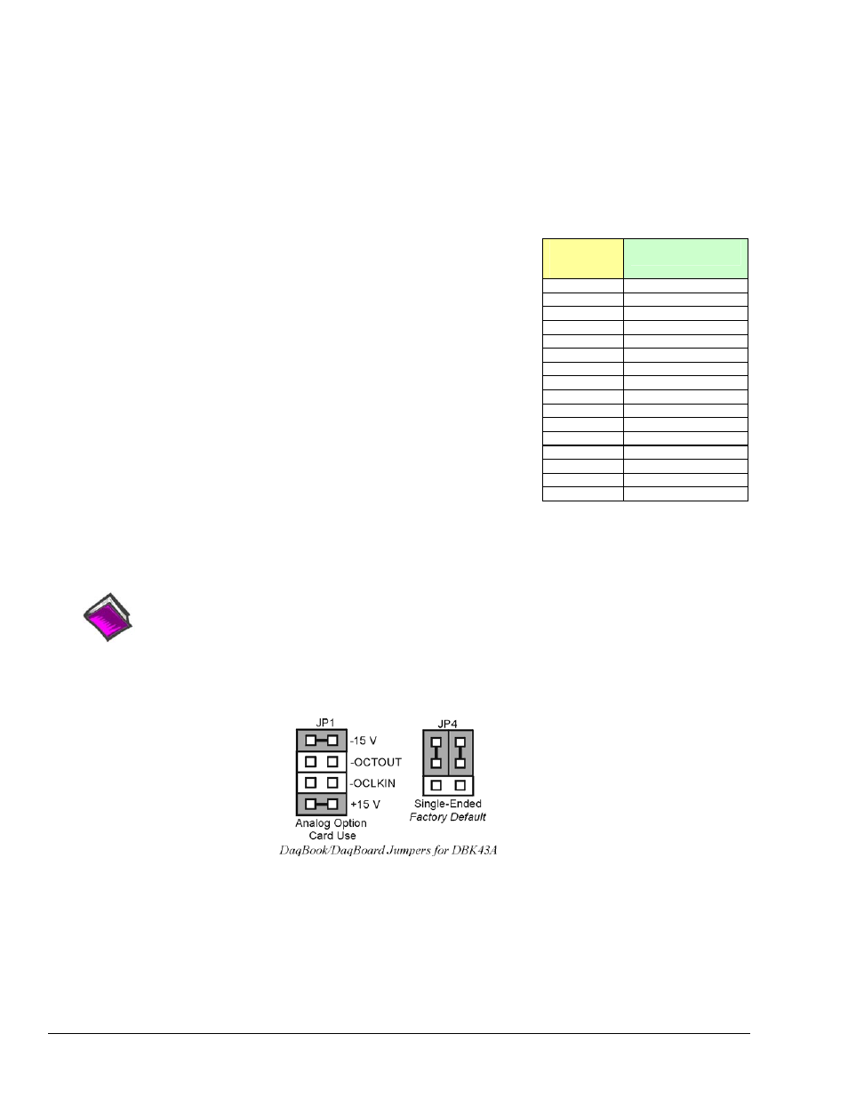
Use of the DBK43A or DBK43B requires setting jumpers in DaqBooks/100 Series & /200 Series devices
and ISA-type DaqBoards.
1. If not using auxiliary power, place the JP1 jumper in the expanded analog mode.
Note: This default position is necessary to power the interface circuitry of the DBK43A [or DBK43B]
via the internal ±15 VDC power supply. If using auxiliary power (DBK32A or DBK33), you
must remove both JP1 jumpers. Refer to Power Management in the DBK Basics section [at the
front of the manual] and to the DBK32A and DBK33 document modules as needed.