Using the db25 signal output connector – Measurement Computing DBK Part 2 User Manual
Page 90
DBK48, pg. 10
967792
8B Isolated Signal Conditioning Module
Using the DB25 Signal Output Connector
Important Notes Regarding the Signal Output Connector
The signal output connector on the rear panel of the DBK48 can be used to directly measure the output
voltage of each 8B module. This applies to input-type modules, i.e., volts, millivolts, thermocouple,
potentiometer, frequency, strain gage, RTD, etc.
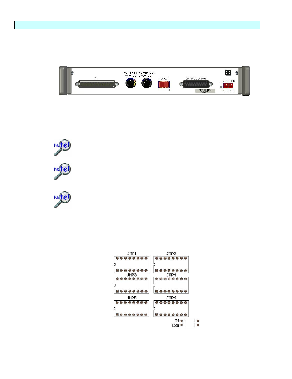
DBK48 Rear Panel
The signal output connector can also be used with output-type 8B modules, e.g., current output and voltage
output. In this case a voltage is applied to the signal output connector. This voltage is converted to an
isolated current or isolated voltage by the 8B module which is installed in that channel. The isolated
current or voltage is available on the front panel terminal block.
Be careful when mixing 8B input modules and 8B output modules.
If possible, do not mix 8B input modules and 8B output modules within the same DBK48.
When applying voltages to the rear panel signal output connector [for 8B output-
modules] it can be easy to short to an adjacent pin on the 25 pin DSUB connector. If
there is an 8B input-module on that channel, damage may occur to that 8B module.
If a voltage source is being applied to a front panel terminal block for an 8B input-type
module and there is an 8B output-type module mistakenly installed in that channel,
damage to the 8B output module may occur.
Configuring the SIGNAL OUTPUT
The signal output connector on the rear panel of the DBK48 can be configured in one of two ways via
jumper networks that are placed in sockets JMP1, 2, 3, 4, 5, and 6.
Signal Output Configuration Jumpers
as Oriented on PCB