Measurement Computing DBK Part 2 User Manual
Page 55
DBK Option Cards and Module
899892
DBK43A & DBK43B, pg. 35
3. Turn off all the channels in the system except for those DBK43A channels that are to be
adjusted.
4. Click the Download button to send the current configuration to the LogBook.
5. Select Indicators \ Enable Input Reading Column from the menu bar to display the values for
each channel.
6. For the associated channel, set the voltage to [G
T
* 0.005] for each transducer by adjusting
the trimpot labeled SCALE. Use the total system gain (G
T
) calculated earlier.
Example
: If G
T
= 435.5, the SCALE trimpot would be adjusted to obtain 2.17 V.
7. Select Indicators \ Disable Input Reading Column from the menu bar.
Trimming Bridge Quiescent Load
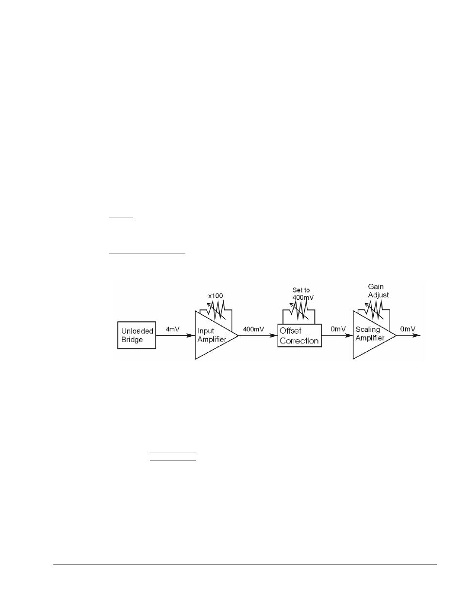
Most bridges have some level of offset, even if no quiescent load is present. In quarter and half bridge
situations, use of 1% bridge completion resistors can cause up to 1mV/V of offset. If the bridge has 4mV
of offset and the Input Amplifier is set to x100, the Offset potentiometer would need to nullify 400mV.
DBK16
– For DBK16s, the Offset Potentiometer can adjust out 0 to +5V of offset amplified by the
Input Amplifier.
DBK43A and DBK43B
– For these two modules, the Offset Potentiometer can adjust out -1.25 to +5V of
offset amplified by the Input Amplifier.
Trimming Bridge Quiescent Load
If a significant amount of quiescent offset is present and the Input Amplifier gain is set too high, the
Offset Potentiometer will not have enough range to adequately nullify the offset. In this case, the gain of
the Input Amplifier must be reduced while the gain of the Scaling Amplifier is increased proportionately.
Use the following steps to trim bridge quiescent load (unload the bridge).
1. DBK43A users: Place the unit’s physical switch to NORM position.
DBK43B users: Place the physical CAL1 and CAL2 switches to the RUN position.
2. In the Param1 column (see page 27 for location), select all of the DBK43A [or DBK43B]
channels that are to be adjusted.
3. Select Mode = Bridge from the drop down list above the grid. This selection commands the
calibration multiplexer to route the transducer output through the analog path as shown
below.