Making terminal block connections, Warning – Measurement Computing DBK Part 2 User Manual
Page 86
DBK48, pg. 6
967792
8B Isolated Signal Conditioning Module
Making Terminal Block Connections
Input signals (and excitation when applicable) are wired to removable terminal blocks. Eight such blocks
can accept 2 channel inputs each. However, only channels 0, 2, 4, 6, 8, 10, 12, and 14 can be connected to
excitation. Thus the DBK48 is limited to 8 strain gages or 8 RTDs as only the even numbered channels
can be connected to excitation.
Each terminal block connects to a signal conditioning module within the DBK48. The blocks accept up to
14-gage wire into quick-connect screw terminals. Wiring schematics are provided below for RTDs,
thermocouples, 20 mA circuits, voltage (mV and V), and for full-bridge and half-bridge strain gages.
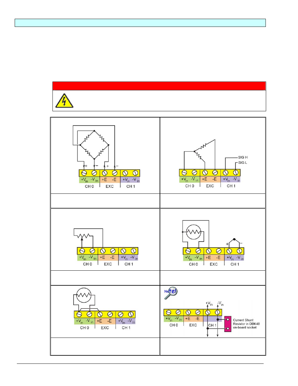
WARNING
Shock Hazard! The DBK48 is designed to sense signals that may carry dangerous
voltages. De-energize circuits connected to the DBK48 before changing the wiring or
configuration.
CH 0 is connected to a Full-Bridge Strain Gage.
CH 1 is shown not connected.
CH 0 is connected to a Half-Bridge Strain Gage.
CH 1 is connected for voltage input (mV or V).
CH 0 has a 3-wire connection to a potentiometer.
CH 1 is shown not connected.
CH 0 has a 3-wire connection to an RTD.
CH 1 is connected to a Thermocouple.
CH 0 has a 2-wire connection to an RTD.
CH 1 is shown not connected.
CH 0 is shown not connected.
CH 1 is connected to a current shunt resistor
resulting in a 4 to 20 mA current loop.
Only current-input type modules require the
plug-in resistors. The plug-in resistors must
be removed for all other module types.