Measurement Computing DBK Part 2 User Manual
Page 219
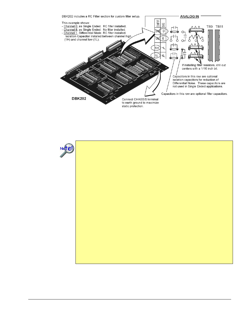
An Example of Customer-Installed Capacitors and Filters for RC Networks on a DBK202
Prior to installing RC components, review the previous WARNING and CAUTION statements; then read
over the following information regarding resistors and capacitors.
•
Do not use RC filters in conjunction with additional DBK expansion accessories.
•
Prior to installing a resistor to the filter network you must drill a 1/16” hole through
the center pinhole [beneath the board’s silkscreen resistor symbol] as indicated in the
above figure. Failure to do so will short-circuit the resistor.
•
Do not drill holes on the board for channels, unless those channels are to receive a
filter network (see preceding statement).
•
Resistors should be ¼ watt, film-type with up to 5% tolerance. Do not use wire-
wound resistor types.
•
A resistor value of 510 Ω is recommended. Do not exceed 510 Ω.
•
Capacitors used are to be of the film dielectric type (e.g., polycarbonate or
NPO ceramic), above 0.001 µF.
•
RECOMMENDED: For reduction of both Common Mode Noise and Differential
Mode Noise, use one capacitor between Channel High and AGND; and use a second
capacitor between Channel Low and AGND.
•
For reduction of Differential Noise [when no reduction of Common Mode Noise is
needed] position a capacitor across the respective Channel High and Channel Low.
•
When in Differential Mode, using capacitors between Channel High, Channel Low,
and AGND may cause a slight degradation of wideband Common Mode rejection.
•
When making a RC filter network, always install a wire jumper between the relevant
FILT CAP LO and AGND. FILT CAP LO terminals are located on TB9 and TB10.
DBK Option Cards and Modules
938994
DBK202, DBK203, and DBK204 Series, pg. 13