Measurement Computing DBK Part 2 User Manual
Page 37
DBK Option Cards and Module
899892
DBK43A & DBK43B, pg. 17
Load Cell Example
Load cells come with a mV/V specification; for each volt of excitation at maximum load, the load
cell will output a specific millivolt level. The following equation applies:
Load Cell Output Voltage = (Load
Applied
/Load
Rated
)(Excitation Voltage)(Load Cell Rating)
For this example, lets assume the following:
• We have a 350 ohm, 3000 pound load cell.
• The load cell is rated at 2.05 mV/V
• We are using an excitation of 10 V
By applying these values to the preceding equation we find that the Load Cell Output Voltage
is 20.5 mV.
Load Cell Output Voltage = (3000/3000)(10)(2.05×10
-3
) = 20.5 mV
For 1000 pounds applied load, the Load Cell Output Voltage would be one third of the 20.5 mV
value, i.e., 20.5 mV/3 = 6.833 mV. If we used the entire equation we would see:
Load Cell Output Voltage = (1000/3000)(10)(2.05×10
-3
) = 6.833 mV
Now that we know our sensor’s full-scale voltage, we can calculate the DBK43 module’s voltage
gain. The proper voltage gain allows the full-scale sensor output to correspond to the full-scale input
of the data acquisition device. Full-scale device inputs are:
-5 to +5 V for DaqBook and DaqBoard [ISA type] in bipolar mode
0 to +10 V for DaqBook, DaqBoard [ISA type], and DaqBoard/2000 Series
in unipolar mode
-10 to +10 V for DaqBoard/2000 Series in bipolar mode and for Daq PC-Card
-10 to +10V for LogBooks in bipolar mode
0 to +20 V for LogBooks in unipolar mode
5. Calculate the channel total gain based on the full-scale LogBook or Daq device.
The following equation is used to calculate DBK43 total gain.
Gain
TOTAL
= (Sensor Output Voltage
FULL-SCALE
– Voltage
OFFSET
) / Strain or Load Voltage
OUTPUT
In this example we will use:
• a full-scale sensor output voltage of +5 V [for a DaqBook in bipolar mode].
• a 0.5 V offset (from full-scale) to prevent saturation
• the 10.5 mV Bridge Output Voltage [for 4000 microstrain] from Example 1.
Using the gain equation we get:
Gain
TOTAL
= (5.0 V – 0.5 V) / 10.5 mV = 4.5 V / 0.0105 V = 428.6
6. Determine how the total gain will be distributed between the input amplifier gain, filter gain, and
scaling amplifier gain.
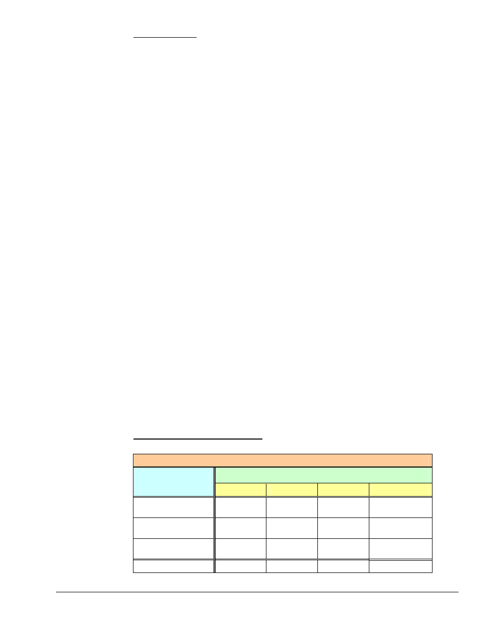
An Example of Total Gain Distribution
: If we round the gain of x428.6 [calculated in the previous
step] down to ×420, then the gain distributions indicated by the following table are possible.
Gain Distribution Options for a Total Gain of x420
Possible Gain Distributions
Gain Stage &
Associated Range
Option A
Option B
Option C
Option D
Input Gain
x100 to x1250
×420 ×100 ×240 ×300
Filter Gain
x1 or x2
Disabled ×2
×1 Disabled
Scaling Gain
x1 to x10
×1 ×2.1
×1.75 ×1.4
Total Gain
×420 ×420 ×420 ×420