Measurement Computing DBK Part 2 User Manual
Page 107
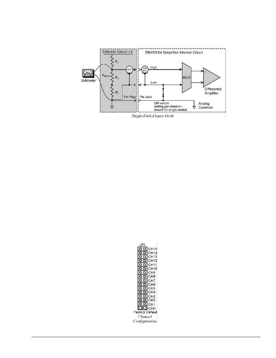
Single-Ended Mode
Ground referencing must also be observed with single-ended measurements. The following figure shows a
typical single-ended hookup.
Module Connection
When connecting analog inputs, carefully consider the requirements for signal connection and ground
referencing. Use BNC-terminated cables (test leads) to interface with the channel inputs. Be sure to
provide the necessary analog common connection.
Module Configuration
Factory Default: Input mode – Single-ended
Up to 16 DBK53s [or DBK54s] may be connected to a primary data acquisition device such as LogBook,
DaqBook, and DaqBoard. As a daisy-chain interface, each module must appear unique; and therefore uses
a different analog input channel identification.
To configure the module:
1.
Assign a channel number to the module. This number must not be used by any other DBK card or
module.
2.
On the DBK53 [or DBK54], locate the 16×2-pin header (JP1).
3.
Place the jumper on the channel you wish to use. The 16 jumper locations on the JP1 header are
labeled CH0 through CH15. Only 1 jumper setting is used on a single module; no other module in
the system can use the same setting.
DBK Option Cards and Modules
989594
DBK53 and DBK54, pg. 3