Measurement Computing DBK Part 2 User Manual
Page 91
8B Isolated Signal Conditioning Module
967792
DKB48, pg. 11
Jumper Assignments
JMP1 JMP2
JMP3
JMP4
JMP5 and JMP6
For JMP1 through JMP6:
CCHx = Single-ended I/O
channel of 8B
Module.
DSUBx = Pin x of the DB25
Signal Output
connector.
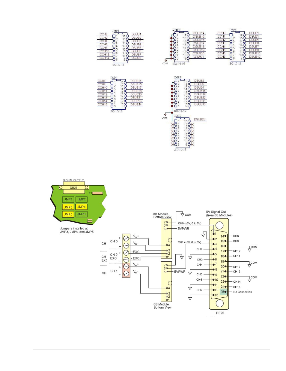
Bringing all Sixteen 8B Module Outputs to the DB25 Signal Output Connector
With three CA-19-8 jumper networks installed [one per socket] in JMP3, JMP4,
and JMP5 the signal output connector is pinned out as shown in the following
figure. This brings the outputs of all sixteen 8B modules to the 25-pin DSUB
Signal Output connector on the rear panel.
DB25 SIGNAL OUTPUT Pinout with JMP3, JMP4, JMP5 Installed
This configuration brings all 16 channel outputs to the DB25 Signal Output Connector.
This manual is related to the following products: