Using the screw-terminal blocks – Measurement Computing DBK Part 2 User Manual
Page 280
DBK214, pg. 6
967894
DBK Option Cards and Modules
Using the Screw-Terminal Blocks
You must remove the DBK214 module’s cover plate to access the screw terminal blocks.
This is described in steps 1 and 2 below.
1.
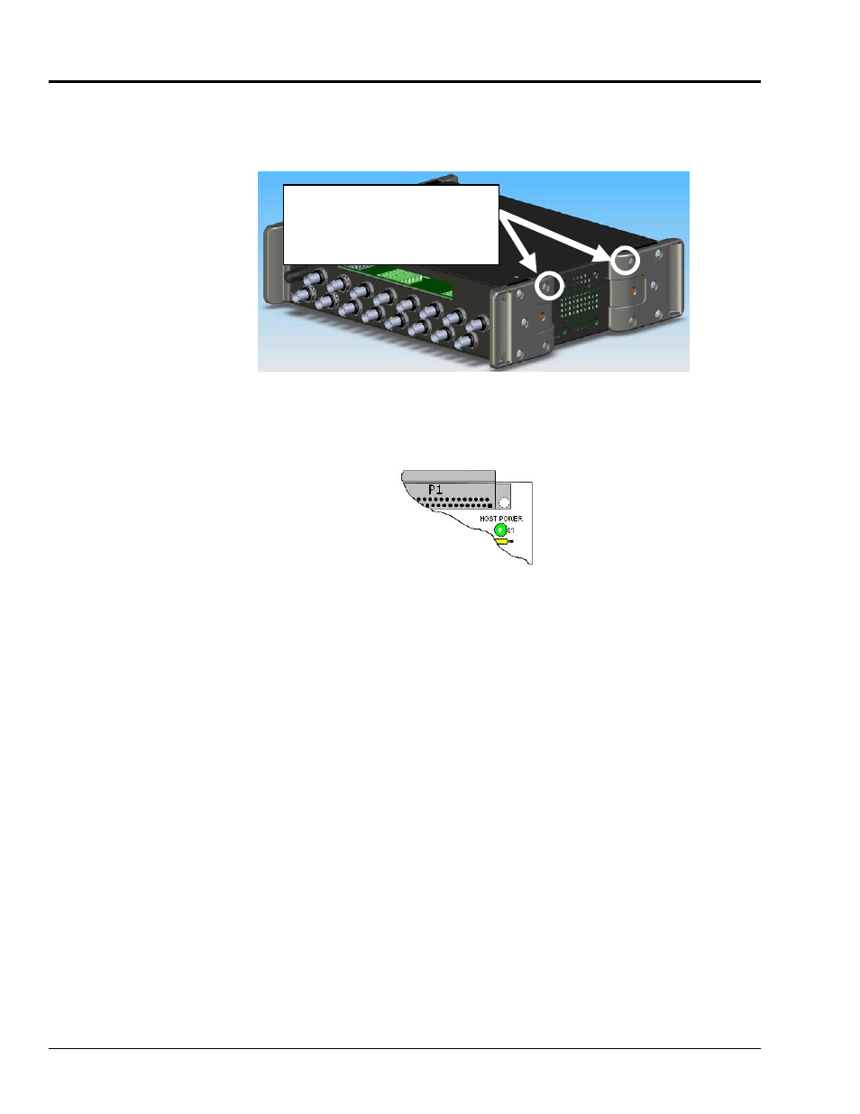
Remove the top inward screws from each of the 4 mounting brackets. See following figure.
The Cover Plate is Secured by 4 Srews
[2 Screws per-side]
To remove the cover plate you
must first remove the top
inward screw from each of the
4 mounting brackets.
2.
After the 4 screws have been removed, carefully remove the cover plate.
3.
As soon as the DBK214 cover is removed, verify that the Host Power LED is “Off.” See
following figure for location.
Host Power LED Location
4.
Make the wiring connections to the terminals. Refer to the board’s silkscreen and to
the pin correlations on the next few pages.
5.
Tighten the terminal block screws snug; but do not over-tighten.
6.
After all terminal connections are made and verified correct, return the cover to the unit and
secure in place with the 4 screws removed earlier. Tighten snug, but do not over-tighten.