Signal connection, Hardware configuration – Measurement Computing DBK Part 2 User Manual
Page 24
DBK43A & DBK43B, pg. 4
899892
DBK Option Cards and Modules
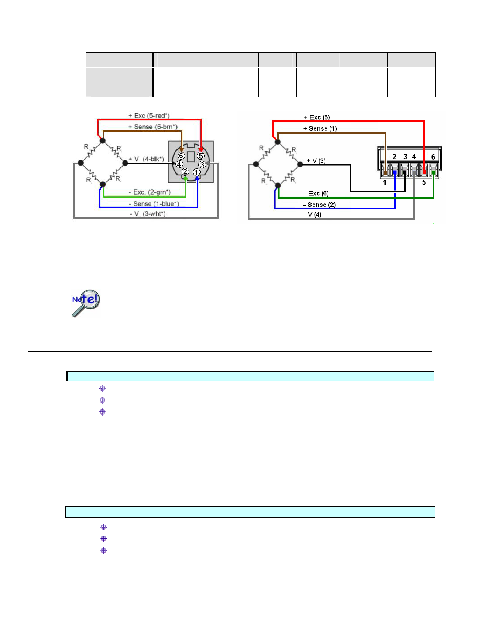
DBK43A uses a mini-DIN6 connector with pre-defined wire color coding based on a CA-132 cable. Color
coding of wires for DBK43B is user-defined.
Pin 1
Pin 2
Pin 3
Pin 4
Pin 5
Pin 6
DBK43A
- Sense
- Exc.
- V
+ V
+ Exc.
+ Sense
DBK43B
+ Sense
- Sense
+ V
- V
+ Exc.
- Exc.
DBK43A Connection Example
Full-Bridge with Remote Sensing
*Colors in this schematic are determined by the Mini-DIN6
connector pin and the color code of the CA-132 cable.
DBK43B Connection Example
Full-Bridge with Remote Sensing
Colors in this schematic are arbitrary.
Actual wiring color is user defined.
The connectivity aspect of DBK43A and DBK43B differs, as indicated in the two wiring
diagrams. Be sure to use the correct diagram for your specific hardware.
The DBK43B pinout and diagram above supersede the one found in the DBK Option Cards
and Modules User’s Manual rev 8.2.
Hardware Configuration
Factory Defaults:
Bridge configuration: Full
Coupling: DC
Low pass filter: Disabled (bypassed)
Unless special arrangements have been made, the cutoff frequency is disabled (bypassed) when
the strain gage module is shipped from the factory. If the low pass filter is enabled it will have a
default value of 3.7 Hz.* You can enable the low pass filter [on an individual channel basis] by
orienting the associated channel’s Filter Jumper (JP104 for channel 0 through JP804 for channel
7) to the vertical position. Refer to the following board layout in regard to jumper location and
orientation.
*DBK43A and DBK43B are shipped with a 100 k
Ω resistor in each of eight channel filter locations. The
resistors are installed in locations R105-106-107 through R805-806-807 (for channels 0 through 7
respectively). Refer to the following board layouts.
Configuration options:
Bridge Applications using various bridge-completion resistors and jumpers
AC Coupling and Low-Pass Filter Options
P1 Output Channel and Card Address Selection
The following board layout can be referred to for jumper, switch, and resistor locations.