Hardware setup, Warning, Caution – Measurement Computing DBK Part 2 User Manual
Page 124
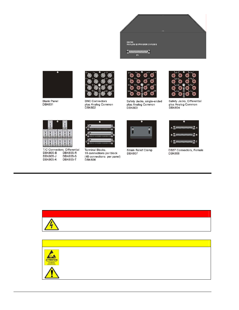
The front panel has a male DB37 connector
that leads to the acquisition processor via a
CA-37-x, CA-37-xT, or equivalent cable.
The rear panel is made of three termination panels with connectors for the various sensors.
Hardware Setup
Hardware setup involves configuring the DBK60, configuring up to three DBK cards that will be used with
the module, installing the DBK cards, then connecting signal lines to the DBK60’s termination panels.
Read over the following WARNING and CAUTION, then complete the steps to successfully setup your
hardware.
WARNING
Electrical Shock Hazard! To avoid injury or equipment damage, turn off power to all
connected equipment during setup.
CAUTION
Use ESD tools, containers, and procedures during setup of DBK cards. Electrostatic
discharge can damage some of the components.
To prevent pin damage, align DBK cards with the backplane DB37 connectors before
gently pressing them together.
DBK60, pg. 2
989594
DBK Option Cards and Modules