Channel configuration, 5b module connection – Measurement Computing DBK Part 2 User Manual
Page 233

Channel Configuration
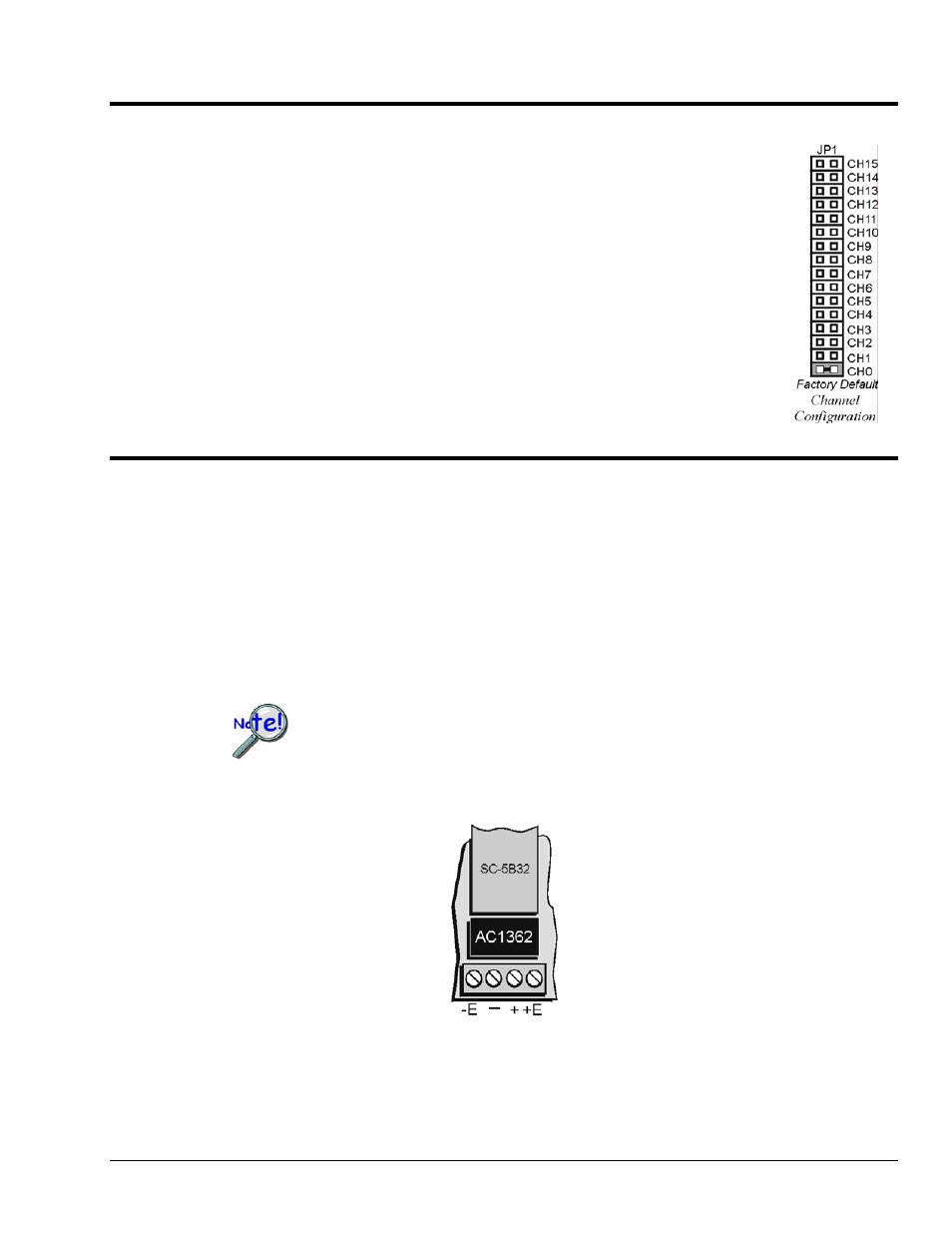
Up to 16 DBK207 [DBK207/CJC] boards can be connected to a Daq-based acquisition
system. Since this is a daisy-chain interface, each module must appear unique and use a
different analog input channel to the Daq device. To configure the board’s channel, you
must set the JP1 jumper to your chosen channel as follows.
1.
Locate the 16×2-pin header (labeled JP1). Note the 16 jumper locations labeled
CH0 through CH15 to match the Daq device’s main channel.
2.
Place the JP1 jumper on the channel you wish to use. Only one jumper is used per
board.
5B Module Connection
DBK207 and DBK207/CJC analog input is processed through user-installed 5B signal-conditioning
modules. Different 5B modules are used with different transducer and signal sources. To install the
modules:
1.
Remove all power from the DBK207 [DBK207/CJC].
2.
Match the footprint of the module with the footprint on the printed circuit board.
3.
Gently place the module into the footprint, and screw it down.
4.
Record the channel the module was placed in.
When installing current input modules (SC-5B32 series), be sure to install the current-
sense resistor (SC-AC-1362 shipped with the SC-5B32) in the resistor socket near the
input screw-terminal block for the desired channel.
AC1362 Current Sense Resistor Install Location
DBK Option Cards and Modules
987594
DBK207 and DBK207/CJC, pg. 5
