Selecting an excitation voltage, Warning – Measurement Computing DBK Part 2 User Manual
Page 131
Selecting an Excitation Voltage
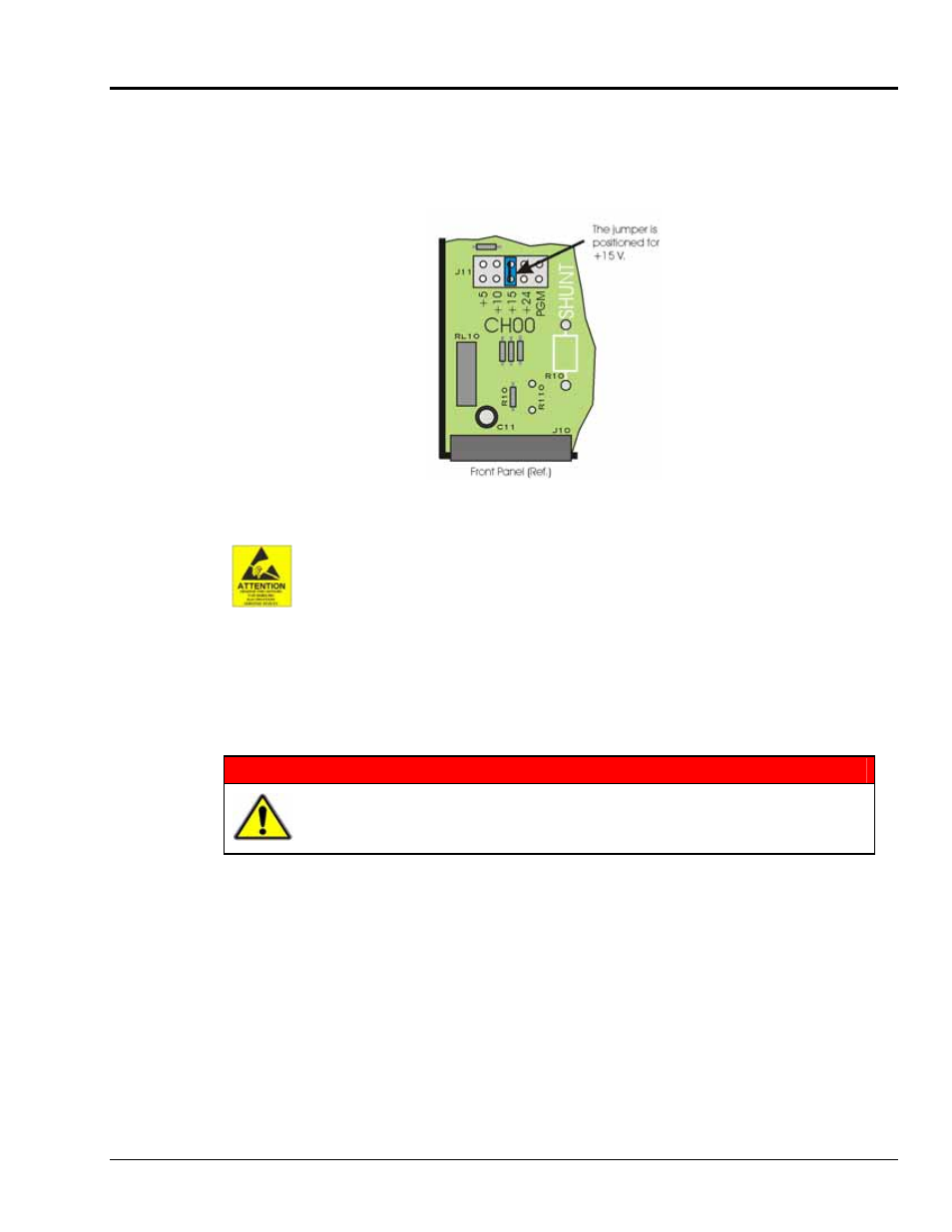
Each channel has a voltage select header, which consists of 5 pairs of pins and a jumper. The jumper
position determines the excitation voltage. Possible voltages are 5, 10, 15, and 24 VDC. A fifth possibility
exists for a custom voltage that resides within the range of 5 to 20 V. To obtain a custom voltage you must
install a resistor in the excitation line labeled “PGM.” The method is discussed shortly.
Reference for Selecting a Pre-Set Voltage Value
The discharge of static electricity can damage some electronic components.
Semiconductor devices are especially susceptible to ESD damage. You should
always handle components carefully, and you should never touch connector pins or
circuit components unless you are following ESD guidelines in an appropriate ESD-
controlled area. Such guidelines include the use of properly grounded mats and
wrist straps, ESD bags and cartons, and related procedures.
WARNING
HOT COMPONENTS! Allow the DBK65 module to cool for at least 30 minutes
before removing the top cover. Some internal components can become very hot
and may cause burns.
To select a pre-set voltage (5, 10, 15, or 24V):
1.
Remove the DBK65 from power and disconnect all signal lines.
2.
Allow the unit to cool for at least 30 minutes.
3.
Remove the 4 screws from the top cover plate. Then remove the plate.
4.
Position the voltage select header’s jumper to the desired setting. See the preceding figure.
5.
Re-install the top cover plate and secure it with the 4 screws that were removed in step 3.
DBK Option Cards and Modules
988793
DBK65 pg. 3