Correlation to p3 – Measurement Computing DBK Part 2 User Manual
Page 284
DBK214, pg. 10
967894
DBK Option Cards and Modules
Correlation to P3
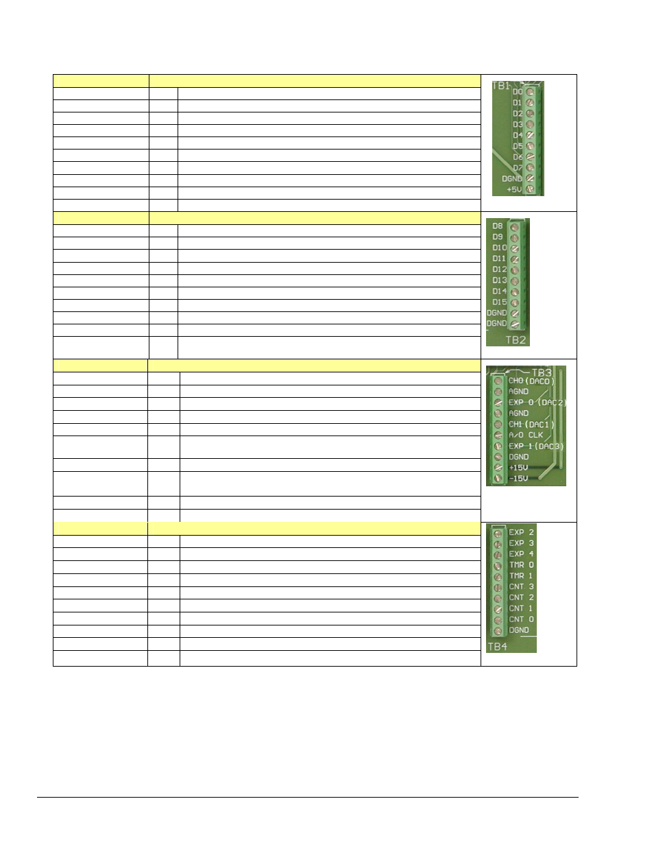
– Pertains to Terminal Blocks TB1, TB2, TB3, and TB4 for Pulse/Frequency/Digital I/O.
TB1
P3 Pin Number and Description
D0
10
P3 Digital Port Bit 0
D1
9
P3 Digital Port Bit 1
D2
8
P3 Digital Port Bit 2
D3
7
P3 Digital Port Bit 3
D4
6
P3 Digital Port Bit 4
D5
5
P3 Digital Port Bit 5
D6
4
P3 Digital Port Bit 6
D7
3
P3 Digital Port Bit 7
DGND
*
Digital Ground, Common
+5V
20
Expansion, +5 Volt Power
P3 – TB1
TB2
P3 Pin Number and Description
D8
29
P3 Digital Port Bit 8
D9
28
P3 Digital Port Bit 9
D10
27
P3 Digital Port Bit 10
D11
26
P3 Digital Port Bit 11
D12
25
P3 Digital Port Bit 12
D13
24
P3 Digital Port Bit 13
D14
23
P3 Digital Port Bit 14
D15
22
P3 Digital Port Bit 15
DGND
*
Digital Ground, Common
DGND
*
Digital Ground, Common
P3 – TB2
TB3
P3 Pin Number and Description
CH0 (DAC0)
34
Analog Out; Analog DAC 0 Output
AGND
*
Analog Ground, Common; intended for use with DACs
EXP 0 (DAC2)
32
Analog Out; Analog DAC 2 Output
AGND
*
Analog Ground, Common; intended for use with DACs
CH1 (DAC1)
33
Analog Out; Analog DAC 1 Output
A/O CLK
21
Analog Out Clock; External DAC Pacer Clock Input/
Internal DAC Pacer Clock Output
EXP 1 (DAC3)
31
Analog Out; Analog DAC 3 Output
DGND
*
Digital Ground, Common
+15 V
19
Expansion, + 15 VDC
-15 V
37
Expansion, -15 VDC
P3 – TB3
TB4
P3 Pin Number and Description
EXP 2
12
Reserved
EXP 3
13
Reserved
EXP 4
14
Reserved
TMR 0
15
P3 Timer 0 Output
TMR 1
16
P3, Timer 1 Output
CNT 3
35
P3 Counter 3 Input
CNT 2
17
P3 Counter 2 Input
CNT 1
36
P3 Counter 1 Input
CNT0
18
P3 Counter 0 Input
DGND
*
Digital Ground, Common
P3 – TB4
*Refer to Ground Correlation Tables in the DBK Options Manual (457-0905), chapter 2, System Connections and Pinouts.