Software-controlled setup – Measurement Computing DBK Part 2 User Manual
Page 34
DBK43A & DBK43B, pg. 14
899892
DBK Option Cards and Modules
Software-Controlled Setup
Proper setup includes the use of software to control the calibration multiplexer in each circuit. The calibration
multiplexer is used to switch the bridge circuit out and apply internal reference voltages to the input for use in
the DBK43A or DBK43B setup. The calibration multiplexer also allows the recording of the individual
adjustments.
The next two tables identify functions available through DaqView and LogView, respectively. Note that
DaqView uses the term “Channel Type;” and LogView uses the term “Mode.” The tables include equations
in which “V
OUT
” (voltage out) represents the voltage recorded by the primary data acquisition device, i.e., a
LogBook, DaqBook, DaqBoard, or other Daq device.
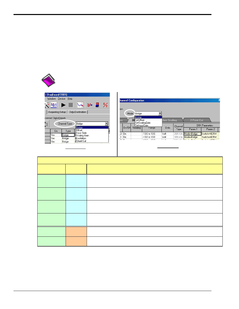
Selecting Channel Types in DaqView, or Modes in LogView
Reference Notes:
Typical setup steps with embedded examples begin on page 16 of this DBK43 document.
The steps can be used for both LogBook and Daq device applications.
Selecting Channel Type for DBK43A
In DaqView
Selecting Channel Mode for DBK43A
In LogView
DBK43A Channel Types and Modes - Switch Positions
Channel Type
1
(Mode)
1
CAL/NORM
Switch
Function and Associated V
OUT
Equation
Bridge
NORM
Sets the channel to read the value of the bridge circuit with all gains and offsets in effect. This is the normal
operation.
Vout = (Scaling Gain)(Filter Gain*)[(InputGain)(bridge circuit voltage) - offset voltage]
Offset
(SetOffset)
NORM
Applies a grounded input to the channel. Sets the channel to read the circuit offset voltage multiplied by the
input amplifier and the low-pass filter gain.
Vout = (Filter Gain*)(Input Gain) - offset voltage
Input Gain
(SetInputGain)
NORM
Applies 5 mV to the input channel. Sets the channel to read the voltage out of the circuit through the input
gain amplifier and the low-pass filter [if enabled].
Vout = (Filter Gain*)(Input Gain)(5 mV) - offset voltage
Scaling Gain
(SetScalingGain)
NORM
Applies 5 mV to the input channel. Sets the channel to read the voltage out of the circuit through the input
gain amplifier, the low-pass filter [if enabled], and the scaling gain amplifier.
Vout = Filter Gain*(Scaling Gain[(Input Gain)(5 mV) - offset voltage])
Excitation
CAL
Sets excitation.
Vout = (Excitation Voltage)
Shunt Cal
CAL
Activates shunt-cal resistors.
Vout = (Scaling Gain)(Filter Gain*)[(Input Gain)( bridge circuit voltage with shunt) - offset voltage]
DBK43A has one CAL/NORM switch. The “Up” position puts the switch in the “calibration” state. The “Down” position puts the
switch in the “Run” (Normal) state. DBK43B has two switches; for that module refer to the following table.
*In the equations, the asterisk indicates the conditional clause, “if the filter is enabled.”
1
DaqView uses the term “Channel Type.” LogView uses the term “Mode.” In the first column the “type” and “mode” names are
often the same for DaqView and LogView. When there are differences the LogView “Mode” name appears in parenthesis, for
example (SetInputGain) is LogView’s mode equivalent of DaqView’s “Input Gain.”