KEYENCE LT-9001 Series User Manual
Page 57
3
Chapter
Operations
and
Fun
ction
Settings
in
the
Displacement
Mo
de
E LT-9001-IM
3-11
The procedure to set [MEASUREMENT] is explained
as follows.
1
Select [OUTPUT] from [OUT1] or [OUT2] on
the program mode screen.
The screen appears for setting the output.
2
Move the cursor over the items for
[MEASUREMENT] by using the [
▲] , [▼] and
[ENTER] buttons.
3
Select either [DISTANCE], [SLANT], [
ΔSLANT]
or [THCIK] by using the [
▲] and [▼] buttons.
4
Press the [ENTER] button.
[MEASUREMENT] setting is fixed.
An error may occur in the thickness measurement of
a transparent object depending on the refractive
index. In such a case, you can use the calibration
function to obtain the proper value.
Refer to "CALIB (calibration)" (page 5-16) for the
calibration function.
The [SLANT] can be set in OUT1 only and cannot be
set in OUT2.
The [SLANT] and [
ΔSLANT] can be selected only
when the scanning width is set to anything other than
[OFF] and [4/1].
Refer to "SCAN" (page 3-15) for setting scanning
width.
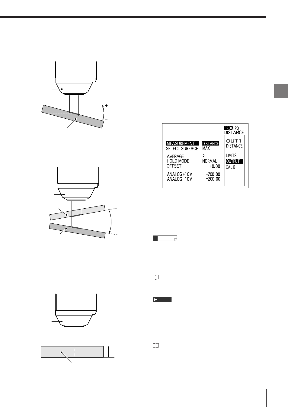
The measuring unit should be viewed in the direction
shown in the drawing. (+/–)
Note
Reference
Slant
The reference surface refers to the surface position
that was adjusted at the factory.
ΔSlant
You can select either surface as a reference surface.
When the target is slanted against the reference
surface in a counterclockwise direction, the value is
regarded as "+", and when the target is slanted in a
clockwise direction, the value is regarded as "–".
Thickness of transparent object (THICK)
The value is always regarded as "+".
Measuring
unit
Measurement target
Degree in relation
to the reference
surface
Measuring
unit
Measurement target
Transparent
target
Relative slant
Measuring
unit
Measuring target (transparent)
Thickness of the
transparent object