Check parameter command format – KEYENCE LT-9001 Series User Manual
Page 145
8
Chapter
RS-232C
8-15
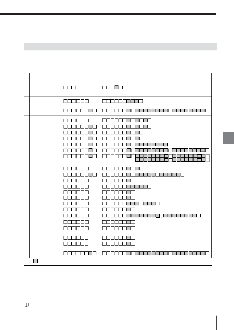
This section describes command format to check the setting contents.
Command list
If the LT-9001 Series receives the response command of the change parameter command as an incoming
command, the parameter will be sent back.
Refer to “Outline of Command Format” (page 8-3) for commands.
* Commands with an asterisk (*) can be used only for the LT-9010 (M).
Check Parameter Command Format
E LT-9001-IM
Incoming command
Response command
Limits
S R
,
F
I
CR
S R
,
F
I
,
o
CR
FINE mode*
S R
,
A V CR
S R
,
A V
,
w CR
Number of times for
averaging*
S R
,
M K CR
S R
,
M K
,
o
CR
Mask
S R
,
D O CR
S R
,
D O
,
o
CR
Dark-out
S R
,
D R CR
S R
,
D R
,
,
r
r
r
r
r
r
CR
Dark-out range
S R
,
A R CR
S R
,
A R
,
s
s
CR
,
Area*
S R
,
S M CR
S R
,
S M
,
w CR
Number of data for smoothing*
S R
,
M S
,
x
CR
S R
,
M S
,
x
,
g
CR
HOLD mode
S R
,
O A
,
x
CR
S R
,
O A
,
x
,
i
CR
Number of times
for averaging
S R
,
S C
,
m CR
S R
,
S C CR
Scan width/interval
Display
Symbol
Program No. check
P R CR
,
d
CR
P R
Analog scaling
S R
,
A S
,
x
CR
S R
,
A S
,
x
,
h
h
h
h
h
h
h
,
h
h
h
h
h
h
h
CR
h
h
Upper/lower limit
S R
,
L M
,
x
CR
S R
,
L M
,
x
,
h
h
h
h
h
h
h
,
h
h
h
h
h
h
h
CR
h
h
Calibration
S R
,
C L
,
x
CR
S R
,
C L
,
x
h
h
h
h
h
h
h
,
,
,
h
h
h
h
h
h
h
,
h
h
h
h
h
h
h
h
h
h
h
h
h
h
CR
h
h
h
h
Mask range
S R
,
M R CR
S R
,
M R
,
,
h
h
h
h
h
h
h
h
h
h
h
h
h
h
CR
h
h
Graph display upper/
lower limit
S
R
,
A A CR
S R
,
A A
,
o CR
Auto slant correction*
S
D
,
S E CR
S D
,
S E
,
o CR
GAIN
S
R
,
,
G L
x
CR
CR
h
h
h
h
h
h
h
h
h
h
h
h
h
h
,
,
S R
,
G L
,
x
h
h
Offset
S R
,
O F
,
x
CR
S R
,
O F
,
x
,
h
h
h
h
h
h
h
CR
h
d : Program number
e : Measurement target
f : Select measurement
g : Measurement mode
hhhhhhhh : Parameter
i : Number of times for averaging n : Run mode
lllll : Scanning position
m : Scan width/interval
o : Operation type
rrr : Light intensity
s : Area setting
t : Area number
w : Smoothing number of times x : OUT number
Scan center position*
S R
,
S
L CR
S R
,
S L
,
l
l
l
l
CR
l
Area range*
S R
,
A W
,
t
CR
CR
S R
,
A W
,
t
,
,
l
l
l
l
l
l
l
l
l
l
P
rogram
Light
intensity
O
U
T
Basic
Optional
Light intensity
level
CR
S R
,
L
T
R
,
,
L T
r
r
r
CR
S
Select surface
S R
,
S U
,
x
CR
S R
S U
,
x
,
e
,
e
CR
,
Run mode/
measurement
S R
,
M D CR
R
,
M D
,
n
,
f
,
f
CR
S
The “ ” portion indicates a parameter or a measured value.