Control i/o, The signal names and descriptions of each terminal, Matching connector specifications – KEYENCE LT-9001 Series User Manual
Page 117
7
Chapter
I/O
Terminal
E LT-9001-IM
7-3
The signal names and descriptions of each terminal
The signal names and descriptions of each terminal are described as follows.
Refer to "Functions of the I/O Signal" (page 7-5) for the detailed functions.
• 24V DC (–) and COM1 are common via a choke coil. Be careful not to generate
a potential difference.
• 0 V for the analog monitor output is isolated from COM1. It is common to the FG
terminal for the AC power supply.
• 24V DC terminal is a dedicated power supply terminal for the monitor specified
by KEYENCE ONLY. Do not use to power other external devices.
The control I/O can be selected from the binary output of the measured value or
the tolerance judgment output depending on the setting.
Refer to "I/O" (page 5-20) for the setting details.
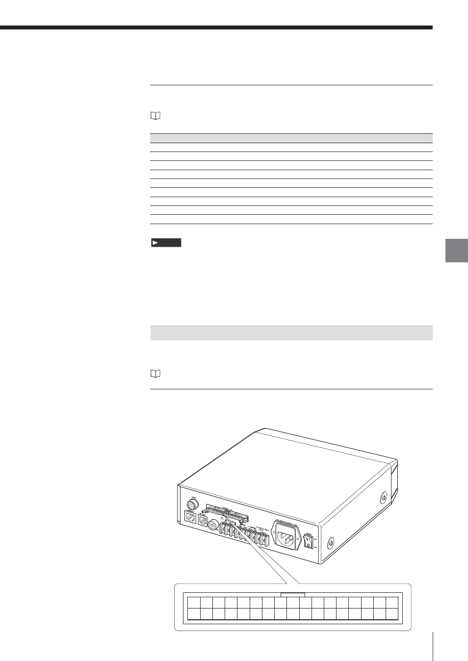
Matching connector specifications
HIROSE Electric HIF3B Series or equivalent
The pin layout is as follows.
Control I/O
Note
Terminal number
Signal name
Description
1
MON1
Analog monitor output1
2
MON2
Analog monitor output2
3
0V
0 V for analog monitor output
4
ZERO
Auto-zero input
5
RESET
Reset input
6
TIMING
Timing input
7
COM1
COM for 4 to 6
8
24V DC (–)
Power (–) terminal for the monitor (CA-MN80)
9
24V DC (+)
Power (+) terminal for the monitor (CA-MN80)
17 16 15 14 13 12 11 10 9 8 7 6 5 4 3 2 1
34 33 32 31 30 29 28 27 26 25 24 23 22 21 20 19 18
Terminal number