Lull 6K Service Manual User Manual
Page 631
Outriggers
Service Manual — Models 644B, 6K, 844C, 8K, 1044C, 10K
10-13
(Ref. Fig. 10-8) The following procedure describes removal of the boom
extension proximity switch.
1. Disconnect the wire harness (Item 4) at the boom extension proximity
switch (Item 2).
2. Place a piece of masking tape around the proximity switch body at the
outer jam nut (Item 3). This will serve as a guide during reinstallation.
3. Remove the inner jam nut (Item 1) and proximity switch. Reinstall the
inner jam nut on the proximity switch for safekeeping.
Installation
Boom Extension
Proximity Switch
(Ref. Fig. 10-8) The following procedure describes installation of the boom
extension proximity switch.
1. Position the outer jam nut (Item 3) on the switch body (Item 2) at the
previously marked position.
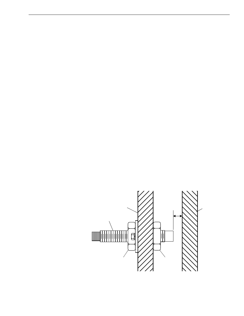
2. Install the boom extension proximity switch in the outer boom. Install
the inner jam nut (Item 1). Check the gap between the end of the
proximity switch and boom. See Fig. 10-9.
3. Connect the wire harness (Item 4) to the proximity switch.
4. Check operation of the proximity switch by extending the boom. The
boom extension proximity light must come on at specified distance
(approximately 21 feet with a tilting tower or 25 feet with a standard
carriage). If the light does not illuminate, stop and retract the boom.
Proceed to “Adjustments” below.
Adjustments
Boom Extension
Proximity Switch
Fig. 10-9: Boom Extension Proximity Switch Adjustment
(Ref. Fig. 10-9) The following procedure describes adjustments to the
boom extension proximity switch.
J
1262
Proximity Switch
Outer Jam Nut
Outer Boom Section
Middle Rear
Boom Section
0.19” to
0.25” Gap
Inner Jam
Nut