Frame tilt lockout valve, Description – Lull 6K Service Manual User Manual
Page 541
Frame Tilt and Oscillation
Service Manual — Models 644B, 6K, 844C, 8K, 1044C, 10K
7-39
15. Lubricate O-rings and backup ring on each check valve cartridge
(Item 21). Install cartridges and torque to 45–50 ft-lbs (540–600 in-lbs).
Check Valve
16. Install check valve (Item 3) in SYS port and torque to 46–50 ft-lbs.
17. For models with control manifold hydraulics, install swivel fitting
(Item 4) on check valve (Item 3). Position fitting as previously noted
and torque to 44–48 ft-lbs.
18. Install adjustable fitting (Item 5) in T port. Position fitting as previously
noted and torque to 300–340 in-lbs (25–29 ft-lbs).
19. If orifice plug (Item 7) was removed (models with control manifold
hydraulics), install it in the elbow (Item 6) so it is finger tight. Then
tighten it 2–3 turns past finger tight. Install the elbow in the PIL port
and torque to 300–340 in-lbs (25–29 ft-lbs).
20. Two (2) O-rings (Item 18) are installed when control block is installed
on rear oscillation lock cylinder. See “Installation” on page 7-35.
Frame Tilt Lockout Valve
Description
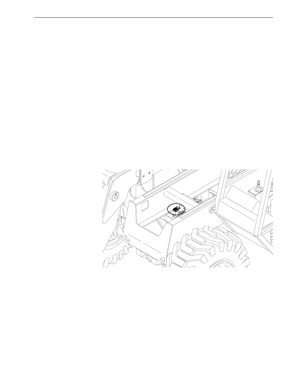
Fig. 7-23: Frame Tilt Lockout Valve
The frame tilt lockout valve is located on the valve plate, near the middle of
the machine. The valve enables/disables frame tilt functions and is a
component of the rear oscillation lock system on early production models
only. See page 7-18 for further information concerning the operation of the
valve.
0
80
60
40
20
-20
K
1033